
Combination of source is grounded and the emitter follower

The described circuit employs an emitter follower (common-collector) configuration to enhance voltage gain while maintaining low output impedance. This arrangement is particularly advantageous in applications where a high input impedance and low output impedance are desired, allowing for effective signal buffering. The grounded source configuration helps stabilize the operation of the field-effect transistor (FET) amplifier, ensuring that the input signal is accurately processed without significant distortion.
In this setup, VTI serves as the vibration-grounded field-effect transistor amplifier, which is responsible for initial signal amplification. The common-collector transistor amplifier (V12) then follows, providing additional gain while ensuring that the output remains stable and capable of driving loads with varying impedance characteristics. The circuit's design emphasizes the importance of low output impedance, which facilitates better power transfer to the load and minimizes signal loss.
When connecting the circuit to a substantial load, such as the European load RL, the voltage gain may initially appear limited. However, the emitter follower's characteristics allow for improved performance under load conditions. This is particularly useful in practical applications where the circuit must interact with real-world components that may introduce additional resistance or reactance.
Overall, the combination of a grounded source and emitter follower configuration with a common-collector transistor amplifier creates a robust circuit capable of delivering reliable performance across various applications. The design principles employed ensure that the circuit can effectively manage both signal integrity and power delivery, making it suitable for a range of electronic systems. Combination of source is grounded and the emitter follower The source is grounded and the emitter with Chong device (common-collector transistor amplifier) combination. As show n in FIG, VTI is vibration grounded field effect transistor amplifier, VI2 as common-collector transistor amplifier. If the circuit is not set vn, but to thousands of European load RL directly as VT1 load, the voltage gain is quite small, with the low output impedance of the emitter follower combination, you get a higher voltage gain, which is the main characteristic of the circuit.
Related Circuits
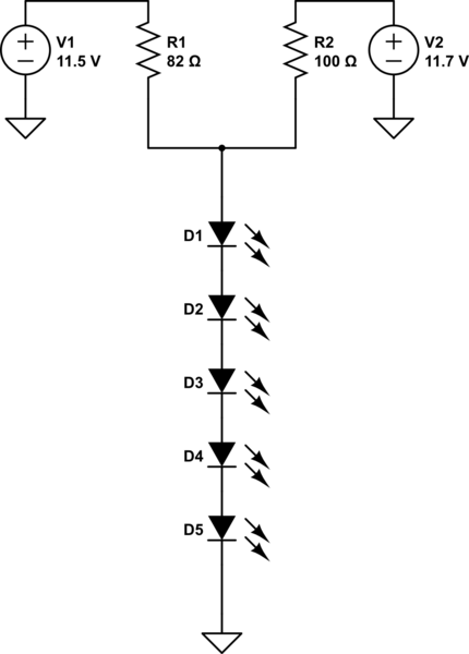
A series of LEDs is intended to display at two brightness levels, and there is uncertainty regarding the proper wiring. This setup is for additional running lights and brake lights on a bicycle. When using the series LED calculator,...

Author Mazi Hosseini describes a simple, low-cost voltage-controlled current source using two operational amplifiers that provides a good range of current and maximum load. The circuit described by Mazi Hosseini utilizes two operational amplifiers (op-amps) to create a voltage-controlled current...
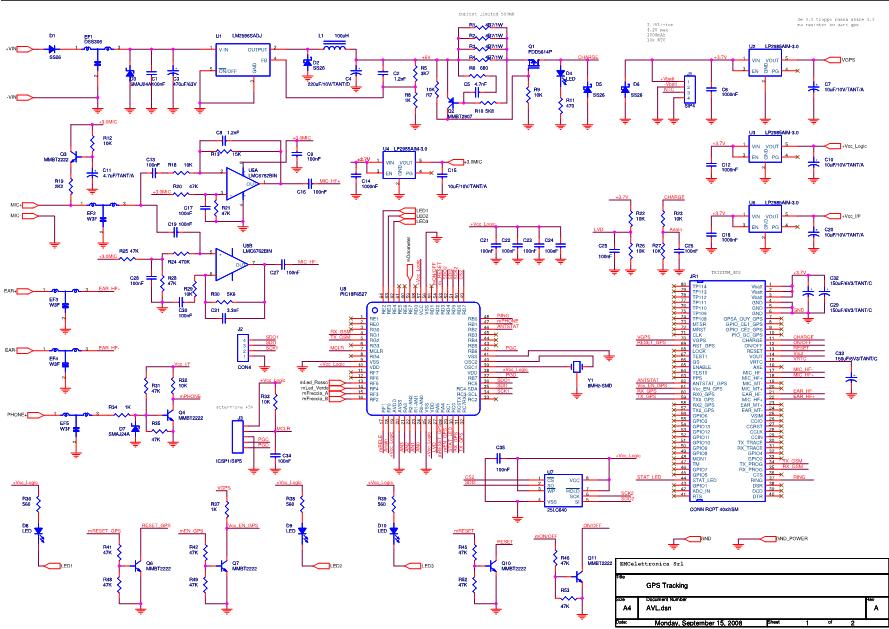
OpenAVL is an open-source project focused on Automatic Vehicle Location (AVL). This project is developed using ANSI C programming language. The prototype board incorporates a low-cost GSM M2M module (MC39i) from Siemens/Cinterion, a GPS OEM module from Leadtek, and...
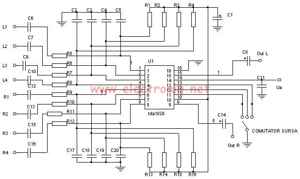
The TDA1029 is a dual operational amplifier configured as an impedance converter. Each amplifier features four mutually switchable inputs that are safeguarded by clamping diodes. Signal sources can be switched in various modes. The electronic components required for this...
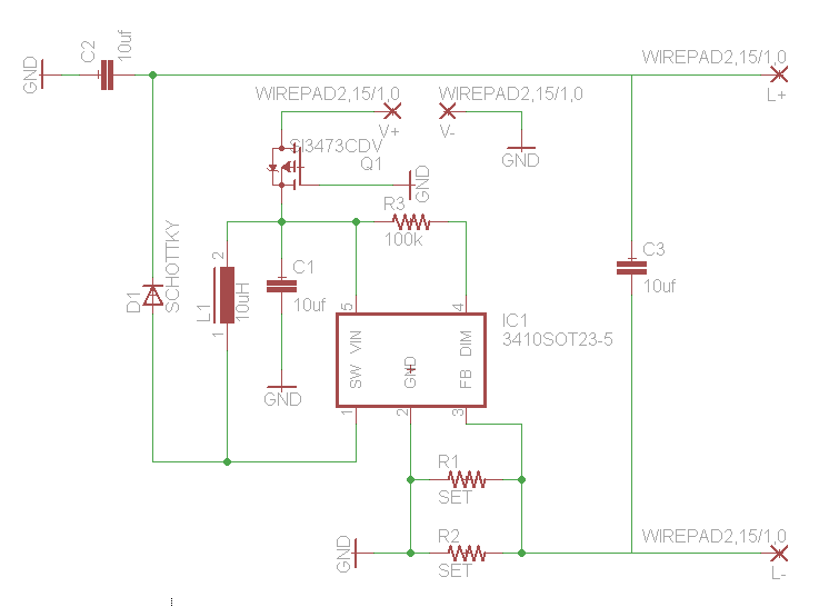
How would you like free boost driver designs? Although it is not possible to control anyone's actions, any individual interested in selling this circuit would be appreciated. The boost driver circuit is a type of DC-DC converter designed to step...
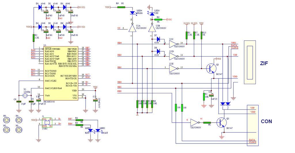
GTP USB PIC Programmer (Open Source). This project includes the GTP USB (not plus or lite). The schematic, photos, and PCB have been developed by PICMASTERS. The GTP USB PIC Programmer is an open-source device designed for programming PIC microcontrollers...