
Atmel 89 Series Flash Programmer Ver 3.0

The ISP programmer serves as a versatile tool for programming Atmel microcontrollers, providing flexibility for both in-system and standalone applications. The in-system programming capability allows for the programming of devices already mounted on a circuit board, facilitating the development and testing of embedded systems without the need for physical removal of the microcontroller. The compatibility with the STK200 hardware ensures that existing users can transition to this programmer with minimal effort, leveraging familiar software tools for the 8051 and AVR series devices.
The inclusion of the 74HCT541 IC is critical for optimal signal integrity. This device functions as a buffer and isolator for the parallel port signals, which is particularly important when interfacing with 3V systems. The use of HCT-type ICs is recommended to ensure reliable operation across various voltage levels, thus preventing signal degradation that could lead to programming errors.
The standalone SPI programmer configuration is designed for simplicity and ease of use, powered directly by the USB port of a PC. This allows for portability and convenience, as users can easily connect the programmer to a laptop or desktop without the need for additional power supplies. The 100mA current limit provided by the USB port is sufficient for programming most Atmel devices, making this solution both effective and efficient.
To operate the programming software, users must ensure that all necessary files from the ISP-3v0.zip package are properly organized within the same folder. The distinction between the executable files for different operating systems underscores the need for compatibility considerations when developing software for a diverse user base. The visual interface of the programming software, as shown in the circuit diagram, is designed to be user-friendly, allowing for straightforward navigation and control of the programming process.
Lastly, caution is advised when programming certain fuses in specific microcontroller models, as incorrect settings can lead to irreversible programming states. The warning regarding the RSTDISBL fuse highlights the importance of understanding fuse settings and their implications on the programming capabilities of the device. Users are encouraged to consult the respective datasheets and programming guidelines to avoid potential pitfalls during the programming process.This ISP Programmer can be used either for in-system programming or as a stand-alone spi programmer for Atmel ISP programmable devices. The programming interface is compatible to STK200 ISP programmer hardware so the users of STK200 can also use the software which can program both the 8051 and AVR series devices.
Figure 1 shows the circuit diagram of the in-system programmer interface, the power to the interface is provided by the target system. The 74HCT541 ic isolate and buffer the parallel port signals. It is necessary to use the HCT type ic in order to make sure the programmer should work with 3v type parallel port. Figure 2 shows the circuit diagram of the stand-alone spi programmer, the power to the interface is provided by the PC USB port which can supply a max of 100mA current.
Get a cheap USB cable, cut the The ISP-3v0. zip file contains the main program and the i/o port driver for windows 2000 & XP. Place all files in the same folder, for win-95/98 use the "ISP-Pgm3v0. exe" file, for win-2000 & XP use the "ISP-XP. bat" file. The main screen view of the program is shown in figure 3. Also make sure do not program the RSTDISBL fuse in ATmega8, ATtiny26 and ATtiny2313 otherwise further spi programming is disable and you will need a parallel programmer to enable the 🔗 External reference
Related Circuits
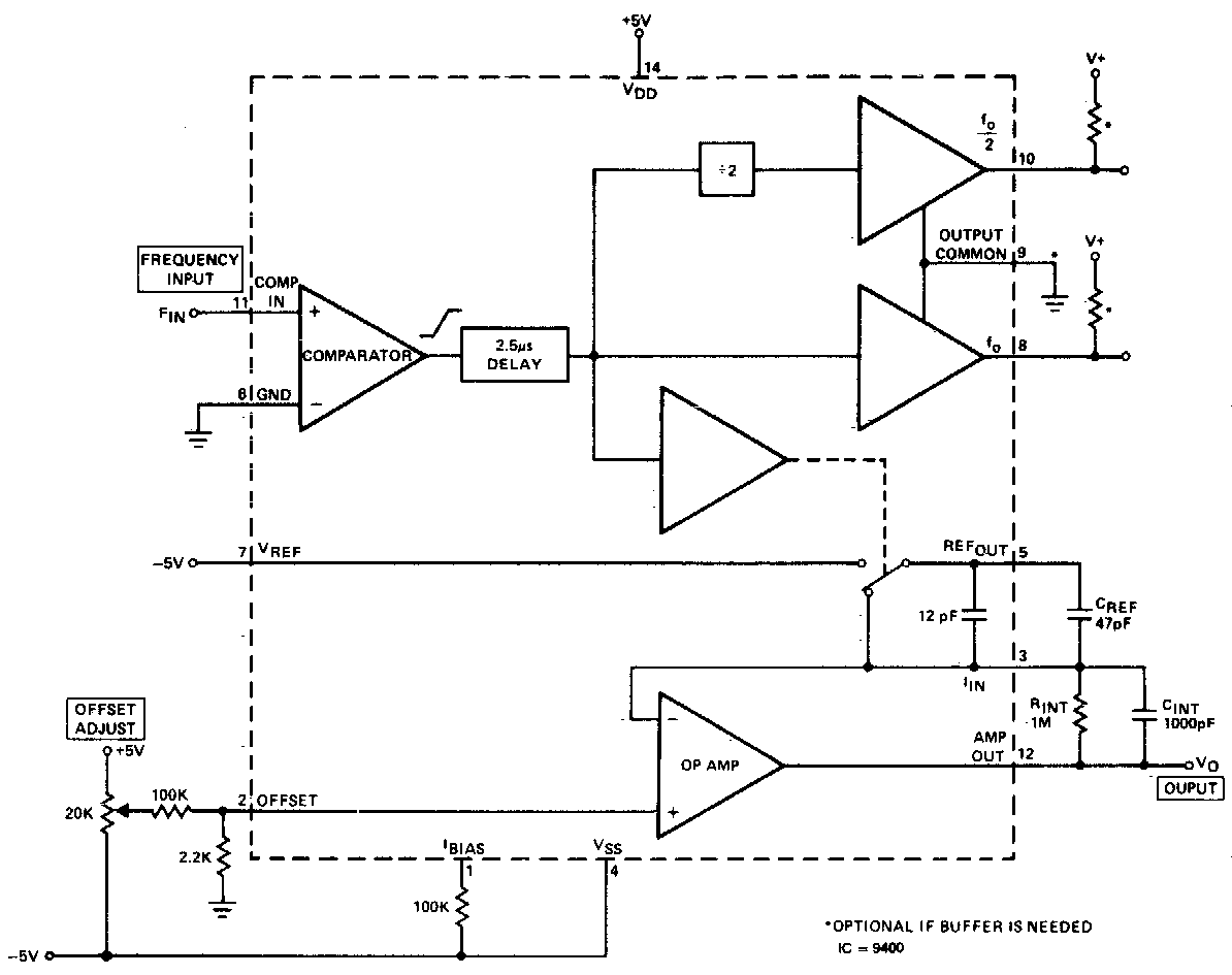
The converter produces an output voltage that is linearly proportional to the input frequency waveform. Each zero crossing at the comparator's input results in a specific change being dispensed into the op-amp's summing junction. This charge subsequently flows through...

A low power, long-life LED flashlight circuit. Electronic Design proposed a simple circuit to resolve this in a recent article. The front end of their circuit draws less than a milliamp of extra current. The described LED flashlight circuit is...

This document does not aim to provide an extensive account of the integrated circuits (ICs) used in this circuit. For additional information on this topic, please refer to the "Flip-Flop Made With A LM556 Timer Chip" section and the...

A signal averager circuit can be formed by an amplifier and active signal rectifier, which is implemented using two operational amplifiers in this circuit. The signal averager circuit utilizes two operational amplifiers (op-amps) to achieve signal averaging through amplification and...

This circuit utilizes a wideband, high slew rate CA3100 BiMOS operational amplifier. The slew rate for this amplifier is 28 V/µs. The output swing is 9 volts peak-to-peak into a terminated line, measured at the termination. The CA3100 BiMOS operational...

This DC to AC inverter circuit operates based on an unstable multivibrator. In this circuit, the IC CD4047 is selected as the core of the unstable multivibrator because this type of IC provides complementary outputs that are out of...