
Loop Control Automatic Reversing Circuit
The circuit design referenced involves the use of specific integrated circuits, notably the LM556 timer chip, which functions as a dual timer. The LM556 can be configured in various modes, including monostable and astable configurations, allowing for flexible applications in timing and pulse generation. In the context of flip-flop designs, this chip can be utilized to create bistable multivibrators, which are essential for storing binary states.
The visible light photo detector circuits mentioned are likely based on photodiodes or phototransistors, which convert light into electrical signals. These components are sensitive to varying light levels and can be integrated with the LM556 timer to create responsive systems that react to changes in illumination, making them suitable for applications such as automatic lighting systems or security alarms.
When designing circuits, it is crucial to consider the layout and the specific characteristics of each component. For instance, the placement of resistors, capacitors, and other passive components can significantly influence the performance of the circuit. The use of breadboards for prototyping is recommended, as it allows for easy modifications and testing of different configurations before finalizing the design.
Additionally, consulting the manufacturer's data sheets is essential for understanding the electrical characteristics, pin configurations, and recommended operating conditions for each component. This information is invaluable for ensuring compatibility and optimizing circuit performance.
In summary, while the provided documentation serves as a guide, it is imperative for users to engage in hands-on experimentation and utilize available resources to achieve successful circuit implementations. The integration of various components, along with a solid understanding of their functions and limitations, will lead to more effective and reliable electronic designs.It is not the purpose of this folio to accommodate a abundant account of the IC`s acclimated by this circuit. If you appetite added advice on this accountable amuse accredit to the Flip-Flop Made With A LM556 Timer Chip folio in the assorted circuits area of this armpit and additionally the Visible Light Photo Detector circuits.
The explanations f or the circuits on these pages cannot achievement to awning every bearings on every layout. For this acumen be able to do some experimenting to get the after-effects you want. This is abnormally accurate of circuits such as the "Across Track Infrared Detection" circuits and any added ambit that relies on added than absolute cyberbanking inputs, such as switches. If you use any of these ambit ideas, ask your genitalia supplier for a archetype of the manufacturers abstracts bedding for any apparatus that you accept not acclimated before.
These bedding accommodate a abundance of abstracts and ambit architecture advice that no cyberbanking or book commodity could access and will save time and conceivably accident to the apparatus themselves. These abstracts bedding can generally be begin on the web armpit of the accessory manufacturers. Although the circuits are anatomic the pages are not meant to be abounding descriptions of anniversary ambit but rather as guides for adapting them for use by others.
If you accept any questions or comments amuse accelerate them to the email abode on the ambit Index page. 🔗 External reference
Related Circuits
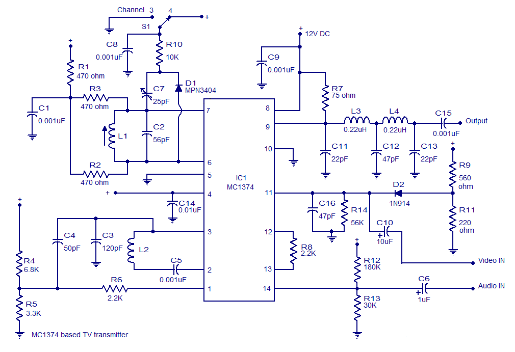
A very simple and high-quality TV transmitter circuit based on the IC MC1374 is presented in this article. The MC1374 is an integrated TV modulator circuit suitable for various TV transmitter applications. It encompasses all necessary circuitry required for...

This circuit outputs the maximum or minimum of four input voltages, V1, V2, V3, and V4. Each of these input voltages ranges from 0 to 5 V. The output of the circuit is the maximum of V1, V2, V3,...

Twenty-five musical keys and 25 LEDs are provided to denote F to F" with half notes in between. Memory can store a played tune. There are ten preprogrammed tunes (each has an average of 55 notes) masked in the...
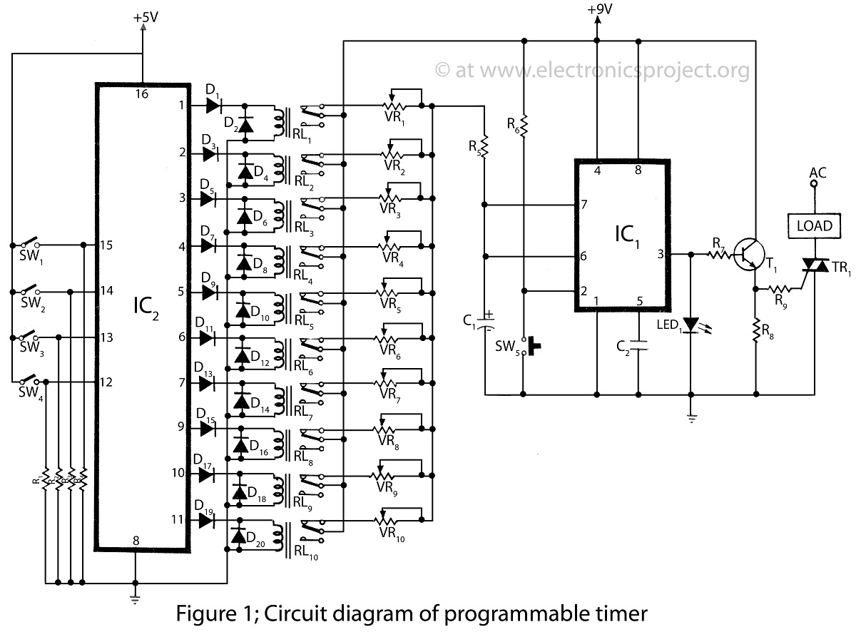
The programmable timer presented on this website is a straightforward design utilizing only two integrated circuits (ICs). It covers a wide range of applications and includes descriptions of various timer projects. The programmable timer circuit typically consists of two primary...

This circuit is used for a Digital Radar Speedometer. It allows for the measurement of the speed of any moving object, particularly vehicles such as cars. The speed is displayed in kilometers per hour (KPH) with a three-digit display....
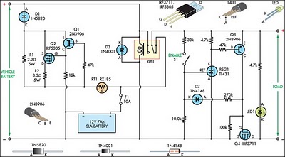
This circuit is designed to switch power to a Peltier cooler in a vehicle. Power is supplied to the load from the vehicle's battery when the ignition switch is on and from an SLA auxiliary battery when the ignition...