
dc to ac inverter with ic cd4047

The described DC to AC inverter circuit utilizes the CD4047 IC, which is known for its versatility in generating square wave outputs through its astable multivibrator configuration. The IC operates by producing two complementary square wave outputs that are 180 degrees out of phase with each other, which is essential for driving a transformer or a load in an inverter application.
The circuit typically consists of the CD4047 connected to a few passive components, such as resistors and capacitors, to set the frequency of oscillation. The values of these components determine the output frequency, which is crucial for matching the inverter's output to the specifications of the intended AC load. The output from pins 10 and 11 can be fed into a transformer, which steps up the voltage to the required level for AC applications.
In addition to the CD4047, the circuit may include additional components such as diodes for protection, capacitors for filtering, and possibly a heat sink for any power transistors used to amplify the output current. The transformer used in the circuit should be rated for the power requirements of the load to ensure efficient operation.
The inverter circuit is particularly useful in applications where DC power, such as from batteries or solar panels, needs to be converted to AC power for household appliances or other AC devices. This design offers a reliable and efficient method to achieve such conversion while maintaining the necessary output characteristics.This DC to AC inverter circuit work based on unstable multi vibrator does. In this circuit, IC CD4047 is chosen as a heart of unstable multivibrator, because this IC type gives a complementary output that has opposite phase to another ( pin 10 and 11 as seen in Figure 1), and has 50 % duty cycle that satisfy to generate a pulse for inverter. 🔗 External reference
Related Circuits
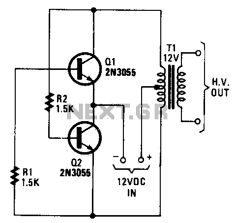
The transformer can be any 6.3 or 12.6 V type. Apply the 12-V DC input so the positive goes to the transformer's center tap and the negative goes to the two transistor emitters. Any bridge-type rectifier and filter can...
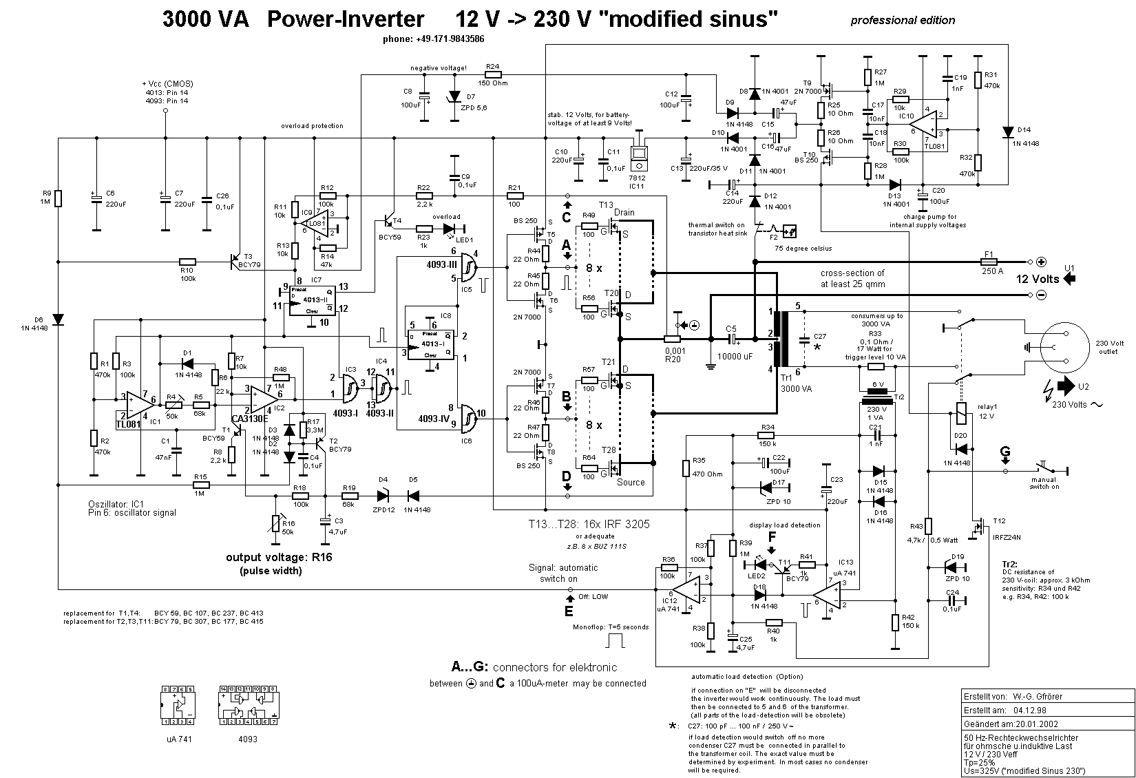
The inverter converts the 12 Volt DC battery voltage into a square wave voltage with a frequency of 50 Hz and a duty cycle of 25%. This voltage is then transformed by transformer Tr1 to 230 Volt RMS. The...

This inverter circuit is designed to power electric razors, stroboscopes, flash tubes, and small fluorescent lamps using a 12-volt car battery. Unlike conventional feedback oscillator inverters, this design features a separate oscillator from the output stage, allowing for easy...
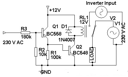
Three weeks ago, an inverter circuit diagram was introduced; however, the circuit did not include the AC to inverter switching part. Today, a 230 Volt AC to inverter switching circuit diagram is being presented. The circuit demonstrates inverter switching....

The inverter described in this text utilizes a MOS field-effect transistor and a standard power transformer. Its output power is determined by the capabilities of both the MOS field-effect transistor and the transformer, eliminating the need for complex voltage...
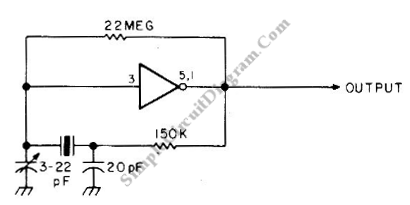
This is an astable multivibrator (oscillator) circuit using a CMOS inverter. The circuit employs the CD4007 or MC14007 integrated circuit. The operating frequency range of this circuit is not specified. The astable multivibrator circuit utilizes CMOS technology to create a...