
Quick Counter For Young Children
The circuit employs a combination of digital logic components and timing elements to create an engaging educational tool. The 4049 hex inverter serves as the primary oscillator, providing clock signals that control the timing of the LED outputs. The 4015 shift registers are pivotal in generating the sequence of LED activations, with the reset mechanism ensuring that the counting sequence can start anew after each cycle. The inclusion of pushbuttons PB1 and PB2 allows for interactive engagement, where children can actively participate in counting and verifying their answers.
The use of a 7555 timer in monostable mode introduces a controlled pulse width, allowing for a brief illumination of the LEDs, which is crucial for maintaining the children's attention and providing a clear counting exercise. The adjustable resistor VR1 enables customization of the viewing time, accommodating different learning paces among children.
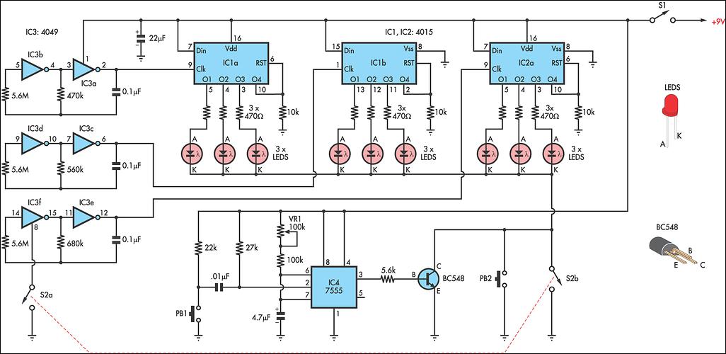
The random arrangement of LEDs in a 3 x 3 grid not only makes the game visually engaging but also enhances cognitive challenges, as children must recognize numbers without relying on spatial patterns. This feature, combined with the non-uniform frequency of number appearances, encourages children to develop their counting skills in a fun and interactive manner, reinforcing their learning through play. Overall, this circuit exemplifies a creative approach to education through electronics, combining fundamental engineering principles with child-friendly design.This circuit is a toy to encourage young children to count. Power is turned on by switch S1, then S2 is closed. This makes nine LEDs flash slowly. S2 is then opened and the LEDs go out. Pressing pushbutton PB1 turns on a random number of LEDs - briefly - during which time they are to be counted. The number counted can be checked by pressing PB2 wh ich turns the same LEDs on for as long as needed. Then repeat. The circuit works as follows: IC3 is a 4049 hex inverter connected as three oscillators running at different rates. It is turned on by closing switch S2a. The clock pulses from IC3 drive both halves of IC1 and one half of IC2, both being 4015 dual 4-stage shift registers.
Each shift register has four outputs which go high in order: 1, 1 and 2; 1 and 2 and 3; 1 and 2 and 3 and 4. However as output 4 is connected to the reset line of its own half - the shift register resets to zero.
Outputs 1, 2 & 3 of all three shift registers are connected to nine LEDs, the cathodes of which go to a common rail. This rail is connected to ground via S2b when switch S2 is closed. When S2 is opened the three oscillators stop but a random number of LEDs is still connected to the high outputs of the 4015s.
That number can be viewed briefly by pressing PB1 which pulses the 7555 timer in monostable mode, to give a short duration output which drives Q1 and connects the LED cathodes to 0V. The viewing time is adjustable by VR1. Checking a count is done by pressing PB2 which holds the same LEDs on as long as desired. The LEDs are set in a 3 x 3 grid with the connection scattered, ie, the first row is not the three LEDs from the first half of IC1.
Note that, unlike the usual dice, a number such as 5 can appear in many formats, so pattern recognition is no help. Also note that this is not a nine output true dice - because the numbers do not come up with equal frequency.
🔗 External reference
Related Circuits
The electronic counter of the winding machine utilizes an LED digital display to indicate the number of turns of the wound coil, with a maximum counting capacity of 9900 turns. The operational principle of the winding machine circuit consists...
A real-time clock turns off the counter at night to conserve power. When a bee crosses under the LED, the light is reflected back to the sensor, which is a phototransistor, and triggers a digital input to the Arduino...
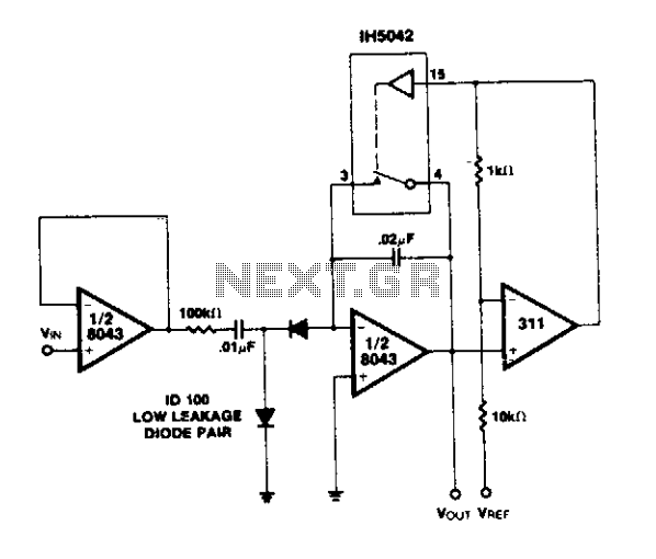
A simple circuit utilizing an LM311 as a level detector and a CMOS analog gate for capacitor discharge is presented. A notable feature of this counter type is the ease of changing the count, which only requires adjusting the...
This is a schematic and block diagram of a 2-MHz frequency counter. It employs an LSI counter/display driver, an LCD readout, and several logic chips for timebase and timing pulse circuitry. Transistors Q2 and Q3 form a signal input...
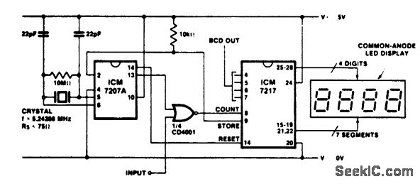
Precision frequency counter/tachometer. The ICM7207A provides a 1-second gating window along with the store and reset signals. The display reads hertz directly. When pin 11 of the ICM7207A is connected to V+, the gating time will be 0.1 seconds,...
This article describes a 2-Digit Counter using a Microchip PIC12F629. It shows what can be done with an 8-pin chip having just 5 output lines and one input line. The chip drives two 7-segment displays and this would normally...