
XOR GATE UP DOWN COUNTER
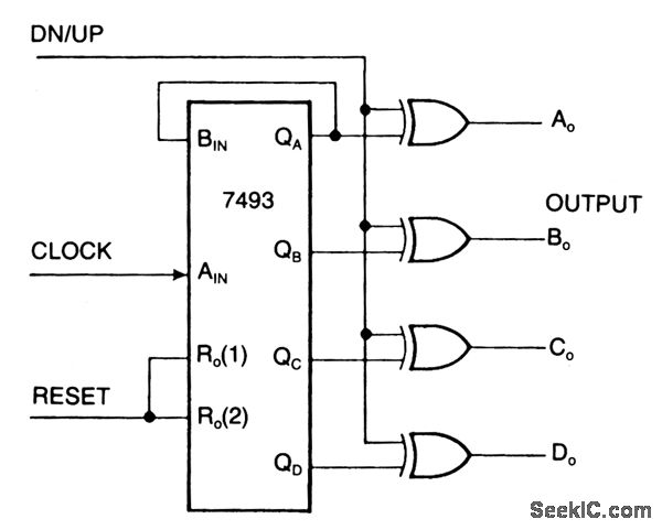
The 7493 binary counter is a versatile component in digital electronics, capable of counting in both ascending and descending order. By incorporating the 7486 XOR gates, the counter can be configured to switch its counting mode based on the state of the DN/UP control line. This flexibility allows for dynamic counting applications where the direction of count may need to be altered based on external conditions.
In the up-count mode, the counter increments its value with each clock pulse applied to the AIN input, while the QA output reflects the least significant bit of the count. When the DN/UP line is asserted low, the counting sequence proceeds from 0 to 15. Conversely, in the down-count mode, when the DN/UP line is high, the counter decrements its value, starting from 15 and counting down to 0.
The reset functionality of the counter is critical for initializing the counting sequence. When the reset input is held high, it not only inhibits the counting operation but also ensures that the outputs are set to a predefined state, either 0 or 15, depending on the counting direction. This reset capability is essential for applications requiring precise control over the counting process.
Cascading multiple 7493 counters enhances the counting range and allows for more complex counting applications. By connecting the QD output of one counter to the clock input of another, a multi-stage counting system can be created, enabling counts beyond the inherent limit of a single counter. This cascading approach is particularly useful in applications such as digital clocks, frequency counters, and event counters, where extended counting capabilities are necessary.
Overall, the combination of the 7493 binary counter and the 7486 XOR gates offers a powerful solution for applications requiring flexible counting mechanisms, with the ability to easily reset and cascade for extended functionality.One can transform an ordinary binary counter, such as a 7493, into an up/down counter with mode control by adding XOR gates 7486 to the counter`s outputs. The circuit counts up when the DN/UP line is low and down when the DN/UP line is high. To use the 7493 counter to count out its maximum count length of 0 - 15, connect the QA output to the BIN i
nput and apply clock pulses to the AIN input. The reset input, when high, inhibits the count inputs and simultaneously retums the outputs AO through DO to low in the up-count mode or 15 in the down-count mode. For normal counting, the reset input must be low. 0ne can easily cascade this counter by feeding the QD line to the clock input of a succeeding counter.
🔗 External reference
Related Circuits
Since then, NL has evolved into the Microsoft Windows®-based NL4, which has been extensively used by world-class engineers in various fields of electronics for almost 10 years. NL5 is the first version to be publicly available. Unlike conventional SPICE-based...
The preamplifier is based on the LM733 or NE592, featuring a bandwidth of 100 MHz. The FET inputs offer an input impedance of approximately 1 MΩ. Signal conditioning is achieved through the use of Q4, Q5, and IC2. The...
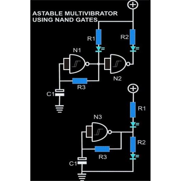
An astable multivibrator is an electronic configuration that generates continuous alternating high and low pulses from two outputs operating in tandem. The IC 4093 consists of four individual NAND gates in one package, specifically Schmitt trigger types, which provide...
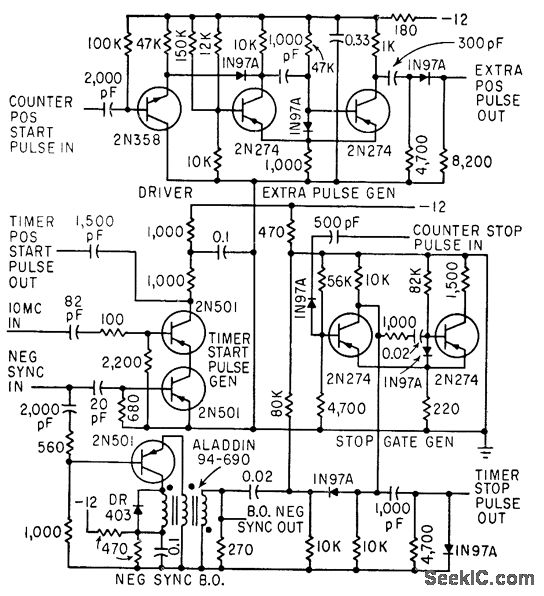
The timer start-pulse generator is a fast series-transistor coincidence circuit. The slope-gate generator is a one-shot multivibrator that prevents the 1N97A diode from passing the blocking oscillator's negative sync pulse until the multivibrator fires. This circuit is utilized to...
In personal electronics and computer audio systems, the SSM2167 is a complete and flexible solution for conditioning microphone inputs. It is also very good for various applications. The SSM2167 is an integrated circuit specifically designed for microphone preamplification and audio...

A Countdown Timer Circuit is a project submitted by a group of students for their ECE 130 - Computer Application class on August 31, 2006, at the University of St. La Salle, Philippines. The seven-segment decoder is utilized in...
Warning: include(partials/cookie-banner.php): Failed to open stream: Permission denied in /var/www/html/nextgr/view-circuit.php on line 713
Warning: include(): Failed opening 'partials/cookie-banner.php' for inclusion (include_path='.:/usr/share/php') in /var/www/html/nextgr/view-circuit.php on line 713