
Stepper motor driver using MC3479

The MC3479 stepper motor driver circuit is designed to efficiently control the operation of a two-phase stepper motor, making it suitable for applications requiring precise positioning and speed control. The device operates in bipolar mode, allowing for bidirectional control of the motor's phases, which is essential for achieving the desired movement and torque characteristics. The compatibility with both TTL and CMOS logic levels ensures that the MC3479 can be integrated into a wide range of digital control systems.
In terms of functionality, the driver utilizes a clock pulse input to dictate the timing of the output changes. This clock pulse can be generated by a microcontroller or other timing circuitry, providing flexibility in controlling the stepper motor's speed and direction. The high-current outputs (L1 to L4) are capable of driving the motor coils directly, enabling robust performance without the need for additional driver stages.
Resistor R1, acting as a pull-up resistor, ensures that the inputs to the MC3479 are held at a defined high state when not actively driven low, preventing floating inputs that could lead to erratic behavior. Resistor Rb is critical for limiting the maximum current that can sink through the outputs, protecting both the driver and the motor from excessive currents that could cause damage.
The inclusion of Zener diode D1 is a vital aspect of the circuit design, as it safeguards the driver from voltage spikes generated by the inductive load of the stepper motor. These back EMF spikes can occur when the motor is switched off or when the direction of current flow is rapidly changed, potentially damaging the integrated circuit. The use of the MC14049UB, a hex inverting buffer, can also help isolate and buffer signals within the circuit, further enhancing reliability and performance.
Overall, this stepper motor driver circuit exemplifies a well-thought-out design that incorporates essential components for effective motor control, ensuring both functionality and protection in various applications.The circuit diagram given here is of a stepper motor driver using MC3479 from Motorola. The MC3479 is specifically designed for driving a 2 phase stepper motor in bipolar mode and is available in standard DIP and surface mount packages. The IC is compatible to TTL and CMOS inputs and has selectable HIGH/LOW output impedance. The output can deliver up to 350mA each of two coils of a 2 phase stepper motor. The state change of the output occurs at the low to high transition of the input clock pulse. The new output will depend on old output and the state of the digital inputs. The output L1 to L4 are high currents outputs, which when connected to a two phase stepper motor forms two full bridge formations. Resistors R1 & Rb, Zener diode D1 and IC2 MC14049UB are the additional components used in the circuit.
R1 is a pull up resistor and Rb is used to set the maximum output sink current. Zener diode D1 provides back emf protection. 🔗 External reference
Related Circuits

In addition to flyback transformers and microwave oven transformers (MOTs), automotive ignition coils are frequently utilized as high voltage sources by various enthusiasts. This is particularly true for the classic cylindrical ignition coils used in carbureted engines prior to...
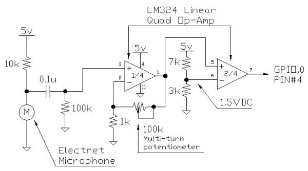
Instructions for creating a Clap-Clap On/Clap-Clap Off switch circuit. This guide provides the necessary information for constructing a clap-activated switch. The Clap-Clap switch circuit is an innovative design that utilizes sound activation to control electronic devices. The primary components of...
This is a circuit to use a standard, low quality opto isolator to transfer an analogue signal with reasonable linearity and without complicated feedback loops to monitor and linearise it. The circuit was designed to interface a mains driven...
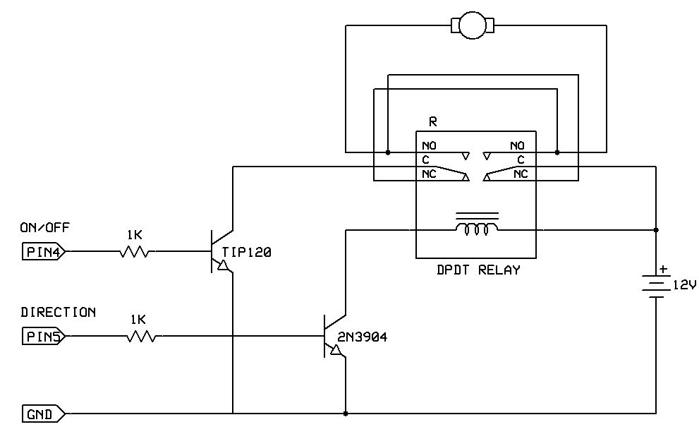
One of the simplest methods to enable a motor to rotate in both directions is by utilizing a double-pole, double-throw (DPDT) relay. This setup requires two transistors and two Stamp pins: one for on/off control and the other for...
This is a simple oscillator with multiple resistors in series. When you press any switch, the circuit starts oscillating. You can use variable resistors instead of the 1k resistors. Using variable resistors, you will be able to tune the...

This series-feedback configuration of components provides a high input impedance and stable, wide-band gain video amplifier suitable for general-purpose applications. Below is the schematic representation of the circuit. The described video amplifier circuit employs a series-feedback topology, which is instrumental...