
ATtiny12 fuse
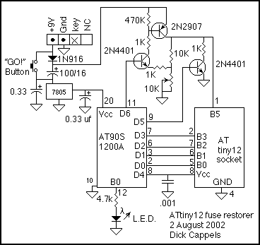
For the details of the programming algorithm, see the Atmel ATtiny12 data sheet. All of the necessary signals are generated by the AT90S1200A, which is clocked by its internal oscillator. If you want to use an AT90S1200 (non-A), you will have to add a crystal or ceramic resonator and load capacitors. The +12V programming voltage is developed in the switched analog regulator made up of the 2N2907 and the 2N4401 that serves as the error amplifier. +17 Volts to supply the switched analog regulator is generated from a 9 volt power supply, in this case, an 8.4 volt Ni-MH transistor radio battery. The 100 uF capacitor charges to the battery voltage through the 1N916 and the internal circuitry inside the 7805. If there is any doubt the capacitor will charge fully, a 1K resistor can be placed from the regulator's input to ground. When the "Go" button is pressed, the charged 100 uF capacitor is placed in series with the 9V battery supply, and the battery is applied to the 7805, thus providing +5V to the logic and +17 volts to the switched 12V supply simultaneously. Since the +12V is only on for a few milliseconds, the voltage on the capacitor does not droop enough during the programming period for the switched 12-volt regulator to go out of regulation.
The AT90S1200 and ATtiny12 sockets must be empty for this procedure. If there are parts in these sockets, they should be removed before starting this procedure.
To execute the programming process, the following steps are crucial:
1. Temporarily but securely jumper the "Go" button. It is advised not to hold it down manually, as intermittent contact may introduce excessive voltage into the circuit.
2. Temporarily but securely jumper Pin 11 of the AT90S1200 socket to Pin 20 of the AT90S1200 socket, which applies +5 volts to the base of the NPN transistor.
3. Apply between +15 and +20 volts DC to the input of the circuit using a bench supply or two 9-volt transistor radio batteries in series.
4. Adjust the 10K potentiometer to obtain +12 volts DC on pin 1 of the ATtiny12 socket.
5. Seal the potentiometer with fingernail polish or glue to prevent accidental adjustment.
6. Remove the +15 to +20 volt power supply.
7. Remove the jumper from Pin 11 of the AT90S1200 socket to Pin 20 of the AT90S1200 socket.
8. Finally, remove the jumper across the "GO" button.
This methodical approach ensures the successful programming of the ATtiny12 microcontroller while maintaining the integrity of the circuit design and components involved.Plug an ATtiny12 into the 8 pin socket and hold down "GO!" button. The LED will come on at the end of the programming process, which only takes a couple hundred millisecond. The fuses are now restored to their factory default states. This picture was taken before the voltage doubler, made with the 1N916 and 100 uf capacitor were added.
The second 2N4401 -the one with the emitter grounded is only there to make sure that pin 1 of the ATtiny12 is pulled to ground when its supposed to be grounded. Note that D9 is set up with a weak pull-up of about 100 uA so that a base resistor is not needed in series with the 2N4401 base.
I didn't use a 2N2907 as the PNP in the circuit I built because I have a bunch of similar transistors with a strange part number (if you have a data sheet for a 2NSA1020Y please contact me) so this aspect has not truly been tested, though the circuit was designed for a 2N2907. For the details of the programming algorithm, see the Atmel ATtiny12 data sheet. All of the necessary signals are generated by the AT90S1200A . which is clocked by its internal oscillator. If you wan to use an AT90S1200 (non-A) you will have to add a crystal or ceramic resonator and load capacitors. The +12v programming voltage is developed in the switched analog regulator made up of the 2N2907 and the 2N4401 that serves as the error amplifier.
+17 Volts to supply the switched analog regulator is generated from a 9 volt power supply, in my case, a 8.4 volt Ni-MH transistor radio battery. The 100 uF capacitor charges to the battery voltage through the 1N916 and the internal circuitry inside the 7805.
If you have any doubt the capacitor will charge fully, you can place a 1K resistor from the regulator's input to ground. When the "Go" button is pressed the charged 100 uf capacitor is placed in series with the 9v battery supply and the battery is applied to the 7805, thus providing +5V to the logic and +17 volts to the switched 12V supply simultaneously.
Since the +12v is only on for a few milliseconds, the voltage on the capacitor does not droop enough during the programming period for the switched 12 volt regulator to go out of regulation. The AT90S1200 and ATtiny12 sockets must be empy for this procedure. If there are parts in these scokets, remove them before startring this procedure. 2. Temporarily but securely jumper the "Go" button. (Do not try just holding it with your finger because to open and close the button during the procedure might cause excessive voltage to appear in the circuit.
3. Temporarily but securely jumper Pin 11 of the AT90S1200 socket to Pin 20 of the AT90S1200 socket (this puts + 5 volts on the base of the NPN transistor.. 4. Apply between +15 and + 20 volts DC to the input of the circuit, by using a bench supply or two 9 volt transistor radio batteries in series.
5. Adjust he 10K pot to obtain + 12 volts DC on pin 1 of the ATtiny12 socket. 6. Seal the pot with fingernail polish or glue. 7. Remove the +15 to + 20 volt power supply. 8. Remove the jumper from Pin 11 of the AT90S1200 socket to pin 20 of the AT90S1200 socket. 9. Remove the jumper across the "GO" button. 🔗 External reference
Related Circuits
The power supply, with electronic stabilization - mainly those of laboratories - should be protected from overcurrent that emanates from short-circuits, erroneous association, or damage of repaired appliances. The circuit offers effective protection in power supply with output voltage...
Life in the 21st century would be almost unbearable without some of the computer peripherals that PC users now look upon as essentials, such as keyboards, mice, and printers. Computer peripherals play a crucial role in enhancing the functionality and...
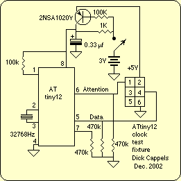
This is the timekeeping test circuit. It includes a one-transistor circuit to switch in the 5V power supply when present and drop back to the 3V battery the rest of the time. That loop of blue wire-wrapping wire is...
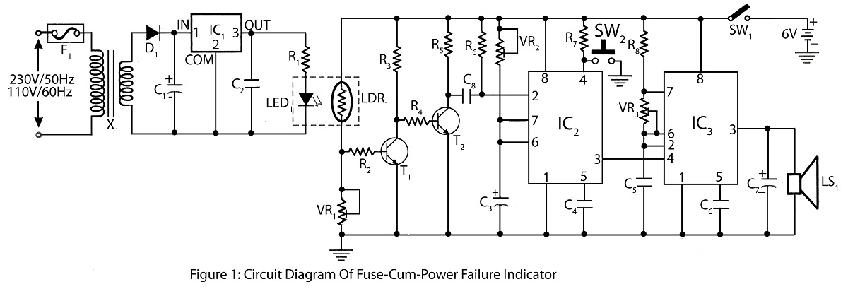
The Fuse Cum Power Failure Indicator utilizes a thermistor and a timer IC (NE555) in its circuit design. The circuit diagram includes a parts list for the fuse cum power failure indicator, which signals instances of power failure. The Fuse...
This circuit is particularly beneficial for hobbyists utilizing a breadboard to experiment with ideas, alongside a simple homemade DC power supply comprising a transformer, rectifier, smoothing capacitor, and protective fuse, which lacks overcurrent protection. In this design, resistor R6...

The AT90S1200 RISC Microprocessor, part of the AVR family, is an efficient component suitable for programming a PLL synthesizer or performing simple tasks within a radio circuit. It is cost-effective, easy to program, and comes with a free integrated...
Warning: include(partials/cookie-banner.php): Failed to open stream: Permission denied in /var/www/html/nextgr/view-circuit.php on line 713
Warning: include(): Failed opening 'partials/cookie-banner.php' for inclusion (include_path='.:/usr/share/php') in /var/www/html/nextgr/view-circuit.php on line 713