
Atv Video Sampler Circuit Circuit
This ATV signal sampling unit is designed to provide high performance with minimal signal degradation, making it suitable for applications requiring precise video transmission. The use of N connectors ensures a robust connection, capable of handling high-frequency signals with low loss. The BNC connector for video output allows for easy integration with standard video equipment, facilitating real-time monitoring and adjustments.
The incorporation of power output meters in both models serves to inform users about the relative strength of the transmitted signal, which is crucial for maintaining optimal transmission conditions. The model with enhanced accuracy is particularly beneficial for professional applications where signal integrity is paramount.
The dual PC controls for video level and power output provide intuitive user interaction, enabling fine-tuning of the system's performance parameters. This feature is essential for achieving the desired video quality and synchronization, ensuring that the output meets the specific requirements of various broadcasting or monitoring scenarios. Overall, this unit is a vital tool for professionals in the field of ATV transmission, offering reliability and precision in signal management. This unit picks up your ATV signal by sampling the transmission line with negligible insertion loss. It uses 2 N connectors for input and output connections. A BNC connector is used on the video output. The detected output is connected to your monitor and scope so that you can accurately adjust your transmitter for proper video and synch levels.
Two different models are provided. Both have relative power output meters, but one has greater accuracy. There are two PC controls, one for video level and the other for power output. 🔗 External reference
Related Circuits
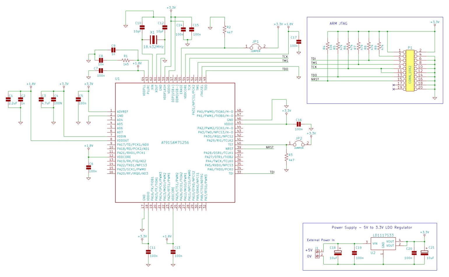
The minimum number of supporting components required to build a circuit using AT91SAM7S microcontrollers. This example uses the AT91SAM7S256 ARM7 microcontroller. To construct a circuit utilizing the AT91SAM7S256 ARM7 microcontroller, a minimal set of supporting components is essential to ensure...
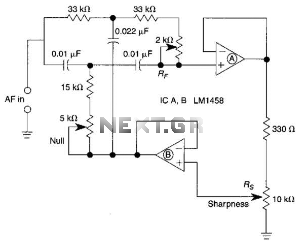
A bootstrapped twin notch filter in this circuit can yield an effective Q of up to 10. Rs adjusts the feedback, hence the Q. Values of C1 and C2 can be changed to alter the frequency. RF is a...

The SN754410 Dual Motor Control circuit is illustrated below. It is straightforward in design, with the PIC serving as the central processor. The main components included in the schematic are the 7805 voltage regulator, the 18F452 microcontroller, and the...
Circuit designed to alleviate concerns related to high frequency utilizes a ready-made module, specifically an Aurel audio FM transmitter. This compact circuit board, measuring 2 cm by 4 cm, supports a modulation frequency track and delivers an RF power...
This toggle circuit utilizes two 555 timers configured as inverters. Pins 2 and 6 serve as the threshold and trigger inputs for the first timer, while pin 5 provides the output. The output at pin 5 will consistently reflect...
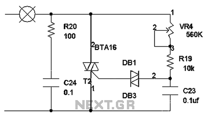
The TRIAC dimmer circuit diagram operates on the principle that a 220V lamp is controlled through the charging of capacitor C23 via resistors VR4 and R19. The charging time is influenced by the values of VR4 and R19, where...
Warning: include(partials/cookie-banner.php): Failed to open stream: Permission denied in /var/www/html/nextgr/view-circuit.php on line 713
Warning: include(): Failed opening 'partials/cookie-banner.php' for inclusion (include_path='.:/usr/share/php') in /var/www/html/nextgr/view-circuit.php on line 713