
Variable Q Filter For 400Hz Circuit
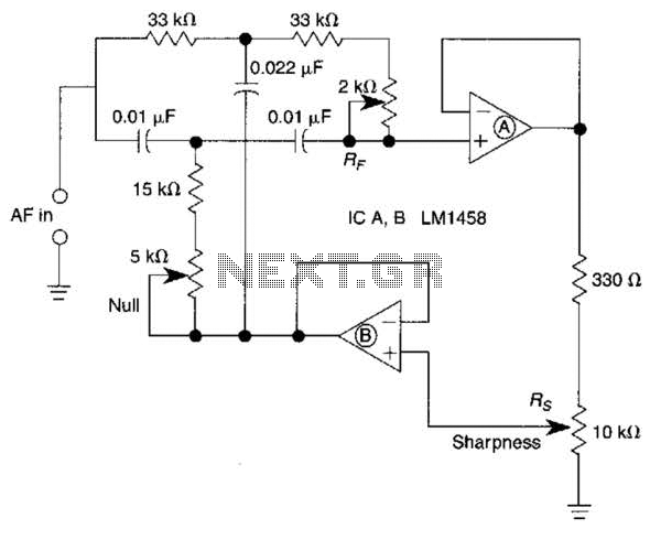
The bootstrapped twin notch filter is a sophisticated circuit configuration designed to achieve high selectivity and precision in filtering specific frequency components from a signal. The effective quality factor (Q) of up to 10 indicates the circuit's ability to provide sharp frequency discrimination, which is essential in applications such as audio processing, communications, and instrumentation.
In this circuit, the resistor Rs plays a crucial role in adjusting the feedback loop, thereby influencing the overall Q factor of the filter. By modifying Rs, the feedback level can be tuned, allowing for precise control over the filter's response characteristics. This adaptability is particularly beneficial in scenarios where the frequency response needs to be optimized for different signal conditions.
Capacitors C1 and C2 are integral to determining the filter's center frequency. By selecting appropriate values for these capacitors, the user can effectively shift the notch frequency to target specific unwanted frequencies within the signal spectrum. This feature enhances the filter's versatility, making it suitable for various applications requiring frequency manipulation.
The RF component serves as a fine-tune null control, providing additional adjustment capabilities to achieve the desired notch depth and position. This control allows for meticulous calibration, ensuring that the filter operates optimally in its intended application.
When designing this circuit, careful consideration should be given to the selection of components to maintain stability and performance across varying operating conditions. Proper layout and grounding techniques are also essential to minimize noise and interference, further enhancing the filter's effectiveness. Overall, the bootstrapped twin notch filter represents a powerful tool for precise frequency management in electronic systems. A bootstrapped twin notch filter in this circuit can yield an effective Q of up to 10. Rs adjusts the feedback, hence the Q. Values of C1 and C2 can be changed to alter the frequency. RF is a fine-tune null control. 🔗 External reference
Related Circuits
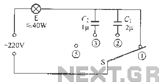
The capacitive dimmer switch circuit is illustrated in Figure 9. It operates based on the principle of capacitive reactance with alternating current. When the switch is in the position shown, the normal light bulb operates at maximum brightness. When...

The circuit below demonstrates the generation of a single positive pulse that is delayed in relation to the trigger input time. It is similar to a previously described circuit but utilizes two stages, allowing for control over both the...
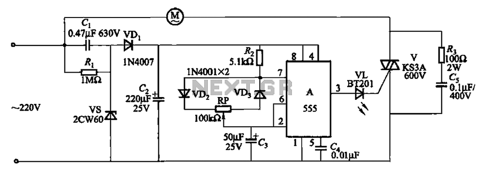
The circuit depicted in Figure 3-8 is designed to control a fan, allowing it to gradually decrease its airflow until it stops completely. This process is repeated in cycles. The circuit utilizes a 555 integrated circuit (IC) configured as...
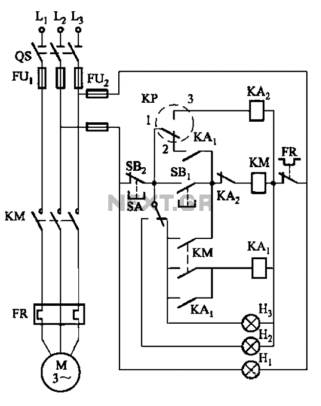
An air compressor is commonly utilized in electrical equipment factories and is typically controlled by electrical contacts. The circuit diagram is depicted in Figure 5-1. The circuit allows for both automatic and manual operation. In the diagram, KP represents...
This weblog discusses electronic circuit schematics, PCB design, DIY kits, and electronic project diagrams. The rain detector operates on the principle of an astable multivibrator using the 555 timer IC, which is equipped with a sensor capable of detecting...
The fundamental issue presented is the perception that logic gates in a circuit seem to generate power from nothing, which contradicts the principles of physics. For instance, consider two NOT gates connected in series. It appears that the first...