
Audible Flasher Warning
The circuit for an automatic turn signal cancellation system is designed to address the issue of riders forgetting to turn off their indicators. This system utilizes a combination of sensors, timers, and microcontroller units to ensure that the turn signals are automatically deactivated after a specified duration or upon detecting a change in direction.
The primary components of the circuit include:
1. **Microcontroller**: A microcontroller serves as the central processing unit, receiving input from various sensors and controlling the turn signal lights. It is programmed to monitor the state of the indicators and determine when to deactivate them.
2. **Accelerometer**: An accelerometer is used to detect changes in motion. When the motorcycle or scooter is turned, the accelerometer senses the change in orientation and sends a signal to the microcontroller.
3. **Timer Circuit**: In addition to motion detection, a timer circuit is implemented to provide a backup mechanism for turn signal cancellation. The timer can be set for a specific duration (e.g., 10 seconds) after the indicator is activated, ensuring that the lights turn off automatically if the rider forgets.
4. **Indicator Lights**: The system interfaces with the motorcycle's existing indicator lights, allowing for seamless integration without requiring extensive modifications.
5. **Power Supply**: The circuit is powered by the motorcycle’s battery, ensuring it operates reliably without the need for additional power sources.
The design must consider factors such as power consumption, environmental resilience, and the ability to operate under various riding conditions. Proper calibration of the accelerometer and timer settings is crucial to ensure that the turn signals deactivate at the appropriate moments, enhancing safety and convenience for riders.
Overall, this automatic turn signal cancellation system significantly improves rider awareness and safety by reducing the likelihood of leaving indicators activated unintentionally.If you re a biker or scooter rider you ll know how easy it is to forget to cancel your flashing indicators after turning without an audible reminder. Cons.. 🔗 External reference
Related Circuits
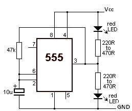
This LED flasher circuit utilizes the 555 timer integrated circuit (IC). The circuit diagram is straightforward and requires only a few external components. When operational, the red LEDs will flash sequentially at a predetermined frequency, similar to the indicators...
200W Lamp Flasher is used to flash lamps, bulbs and halogen lamp to give your product that attracting look. More: Input supply - 6 ~ 12 VDC Output - upto 200 W lamp / bulb load Optically isolated Mains supply Onboard preset...
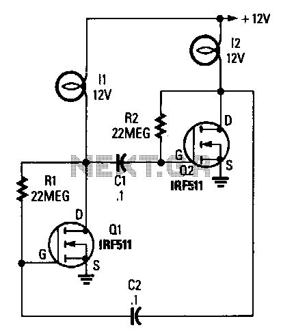
The circuit consists of two power FETs configured as a simple astable multivibrator to alternately switch two lamps on and off. The resistor-capacitor (RC) values set the flash rate to approximately 1/3 Hz. By varying either the resistor or...
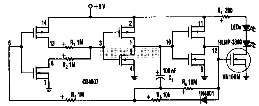
Inserting two 1-MΩ resistors, R1 and R2, in the output stage of one of the circuit's inverters limits the current needed by the oscillator tone to more than a few pA. This circuit includes a CD4007 package, which contains...
This continuity tester circuit allows for the examination of PCB track failures without the need to visually inspect the routing of the tracks, which can often be frustrating. The continuity tester circuit is designed to facilitate the detection of faults...

This circuit diagram represents a lamp flasher powered by mains electricity. It is capable of flashing lamps with a maximum power of 200 Watts at user-defined rates. The NE555 integrated circuit is configured as an astable multivibrator, generating the...
Warning: include(partials/cookie-banner.php): Failed to open stream: Permission denied in /var/www/html/nextgr/view-circuit.php on line 713
Warning: include(): Failed opening 'partials/cookie-banner.php' for inclusion (include_path='.:/usr/share/php') in /var/www/html/nextgr/view-circuit.php on line 713