
Voltage and Current Limited Audible Continuity Tester
The continuity tester circuit is designed to facilitate the detection of faults in printed circuit board (PCB) tracks by providing a simple and effective means of testing connectivity. The circuit typically consists of a power source, a resistor, an LED indicator, and a testing probe.
When the circuit is powered, the LED indicator remains off, signifying that there is no continuity. When the testing probe contacts a point on the PCB track, the circuit path is completed if the track is intact. This completion allows current to flow through the resistor, illuminating the LED. The brightness of the LED can provide an indication of the quality of the connection; a dim light may suggest a weak connection, while a bright light indicates a strong, intact track.
The inclusion of a buzzer or audible indicator can enhance the functionality of the tester by providing an additional alert when continuity is detected. This feature is particularly useful in noisy environments where visual indicators may not be easily noticed.
The circuit can be powered by a standard battery, ensuring portability and ease of use in various settings. The design can be further refined by incorporating a microcontroller for advanced features such as automatic testing sequences, logging results, or integrating with a computer for data analysis.
Overall, the continuity tester circuit is an essential tool for electronics engineers and technicians, enabling efficient troubleshooting and maintenance of PCB assemblies without the need for direct visual inspection.Using this continuity tester circuit, a failure of? PCB tracks be examined without looking directly at the tracks routing, which is can be very frustrating 🔗 External reference
Related Circuits

This circuit design for a low current relay is intended for use in battery-operated electronic devices, with an operating current in microamperes (µA). It utilizes a bistable relay and additional components to enable the relay to function similarly to...

A simple yet reliable car battery tester circuit diagram. This circuit utilizes the popular and easily accessible LM3914 integrated circuit (IC). The LM3914 is straightforward to operate, does not require external voltage regulators due to its built-in voltage regulator,...
The circuit is designed for high precision operation over an extended temperature range, provided that V+ remains relatively constant, as the current IZ is dependent on V+. Resistors R1, R2, R3, and R4 are selected to ensure the appropriate...

This is a small circuit designed for use as a charging controller or voltage limiter. It is particularly useful for creating a solar charger. The assembly of the circuit allows for modifications according to personal preferences. The circuit is...
Many analog ohm meters have a non-linear scale, which results in poorer resolution at higher resistance values. This is due to the use of inexpensive current sources. Many analog ohm meters operate on a principle where the scale is not...
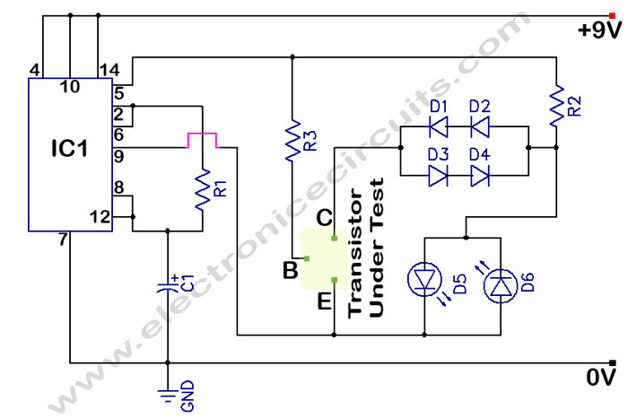
The circuit is a transistor tester schematic that indicates the condition of a transistor using two LEDs. It is designed to test a good NPN transistor. The transistor tester circuit operates by utilizing two light-emitting diodes (LEDs) to provide a...