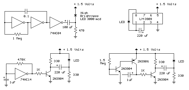
Door Ajar Light Flasher

A magnet is positioned on the door, while a magnetic reed switch is installed on the door casing. When the door is closed, the circuit is disabled. When the door is opened, the circuit becomes active.
In this circuit design, the integration of a magnet and a magnetic reed switch serves as a simple yet effective door status indicator. The magnetic reed switch is a type of sensor that operates on the principle of magnetism. It consists of two ferromagnetic contacts sealed within a glass tube. When a magnetic field is present, as provided by the magnet attached to the door, the contacts close, completing the circuit. Conversely, when the door opens and the magnet moves away from the switch, the magnetic field dissipates, causing the contacts to open and thereby disabling the circuit.
This configuration can be utilized in various applications, including security systems, alarm systems, and automated door controls. The circuit can be connected to a variety of output devices, such as an LED indicator, a buzzer, or a microcontroller input, to signal the door's status.
To enhance functionality, additional components can be incorporated. For instance, a pull-up resistor can be added to ensure that the circuit remains in a defined state when the reed switch is open. A debounce circuit may also be implemented to prevent false triggering caused by mechanical vibrations when the door is closed or opened.
In summary, the combination of a magnet and a magnetic reed switch provides a reliable mechanism for detecting door status, making it a valuable component in electronic circuit designs aimed at security and automation.A magnet is placed on the door and a magnetic reed switch on the door casing so when the door is closed the circuit is disabled. When the door is open, the.. 🔗 External reference


