
audible logic pulses
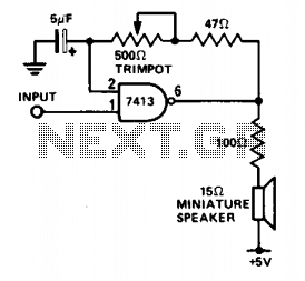
The described circuit utilizes a Schmitt trigger configured as an oscillator to monitor slow logic pulses effectively. It serves dual purposes: functioning as a keying monitor and acting as a digital clock alarm. The Schmitt trigger's inherent hysteresis provides stable switching characteristics, which are essential for distinguishing between high and low logic levels, particularly in slow pulse applications.
The circuit incorporates a trimpot (trimming potentiometer) that allows for precise adjustment of the output frequency or pitch. This feature is particularly useful in applications where specific timing or frequency characteristics are required. As the input signal transitions to a high state, the oscillator becomes activated, producing an oscillating output.
In terms of implementation, the Schmitt trigger is typically connected in a feedback configuration, which establishes the oscillation. The output frequency can be adjusted by varying the resistance of the trimpot, thus changing the charge and discharge times of the timing capacitor in the circuit. This adjustment enables fine-tuning of the oscillation period, allowing the circuit to adapt to different monitoring needs or alarm conditions.
Overall, this circuit design exemplifies a versatile approach to pulse monitoring, leveraging the reliable properties of the Schmitt trigger and the adjustable nature of the trimpot to meet various application requirements.This circuit is useful for monitoring slow logic pulses as a keying monitor or digital clock alarm. The Schmitt trigger is connected as an oscillator. The trimpot controls the pitch of the output. When the input goes high, the circuit will oscillate. 🔗 External reference
Related Circuits
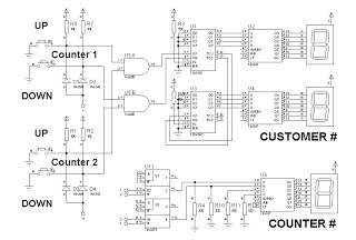
This is a simplified design utilizing an up/down counter integrated circuit (IC), specifically the 74192. This versatile logic IC features separate pins for counting both up and down. Additionally, an RS latch is incorporated to indicate the current counter...
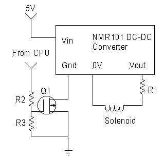
Despite exhaustive searching, every reasonably priced solenoid valve for controlling propane during pushbutton start required 12VDC, beyond the capabilities of a normal pump battery. There are methods to generate HV pulses which will actuate the solenoid, which will remain...
The 5 volt regulated power supply for TTL and 74LS series integrated circuits has to be very precise and tolerant of voltage transients. These ICs are easily damaged by short voltage spikes. A fuse will blow when its current...
This precise one-pulse-per-second clock is constructed using a few common components and is driven by a 50 or 60 Hertz mains supply, without any direct connection to it. It produces a beep or metronome-like click and/or a visible flash...
The 741 operational amplifier is configured as an audio oscillator utilizing Radio Shack 276-677 photocells within the feedback circuit. When light illuminates PC1, its resistance diminishes, leading to a corresponding decrease in the frequency of the audio tone heard...
A logic indicator circuit, also known as a logic probe, is utilized to identify the logic level at any point within a logic circuit. The indicator can be visual, employing components such as LEDs, LCDs, or seven-segment displays. The logic...
Warning: include(partials/cookie-banner.php): Failed to open stream: Permission denied in /var/www/html/nextgr/view-circuit.php on line 713
Warning: include(): Failed opening 'partials/cookie-banner.php' for inclusion (include_path='.:/usr/share/php') in /var/www/html/nextgr/view-circuit.php on line 713