
Audio Alarm Circuit
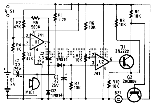
The circuit operates as an audio level detector and alarm system, utilizing a combination of amplification, rectification, and signal processing to monitor ambient sound levels. The condenser microphone (U1) is the primary sensing element, converting acoustic signals into electrical signals. The output from U1 is conditioned by resistors R1, R2, and R3, which manage current flow and set the output voltage range, ensuring compatibility with single-ended power supplies. The rectification process performed by diodes D1 and D2 transforms the AC signal into a pulsating DC signal, which is then smoothed out by capacitor C3, providing a stable DC voltage that reflects the ambient sound level.
The operational amplifier U2 is configured in a comparator mode, comparing the processed voltage from the microphone with a reference voltage established by R11. The reference voltage can be adjusted to set a threshold for sound detection. When the ambient noise level exceeds this threshold, the output of U2 shifts from low to high, indicating that a significant sound event has occurred.
Transistor Q1 serves as a switch, initially biased into a partially on state by the low output from U2, while the voltage divider formed by R8 and R10 ensures that Q2 remains off during low noise conditions. Upon detection of elevated noise levels, Q1 is fully turned on, which in turn activates Q2. This action drives the piezo buzzer to emit sound, alerting users to the detected noise.
Overall, this circuit effectively combines audio sensing, signal processing, and alarm activation in a compact design, suitable for applications such as noise monitoring systems, alarms, and other sound-activated devices. In the circuit, U1 amplifies the audio picked up by the condenser microphone. Resistor Rl limits current, while R2 and R3 center the output of the amplifier to %B+ to allow a single-ended supply to be used. Diodes D1 and D2 rectify the output of Ul, and C3 filters the resulting pulsing dc. Thus, a dc voltage that is proportional to the ambient sound level is produced.That voltage is presented to the noninverting input of U2.
The inverting input is provided with a reference voltage of between 0 and lAB+, which is set by Rll.As long as the noise level is low enough to keep the voltage at pin 3 lower than the voltage at pin 2, the output of U2 stays low (approximately 1 V). That is enough to bias Ql partially on. A voltage divider, formed by R8/R10 and Ql (when it`s partially on), prevents Q2 from turning on.When the noise level is high enough to bring the voltage at pin 3 higher than the voltage at pin 2, the output of U2 goes high. That turns Ql fully on and drives Q2 into saturation. The piezo buzzer then sounds until the power is cut off. 🔗 External reference
Related Circuits
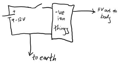
This article demonstrates how to create a simple yet effective static electricity generator. This device enables the user to carry a constant static charge on their body and discharge it onto anything grounded or of opposite polarity. The generated...
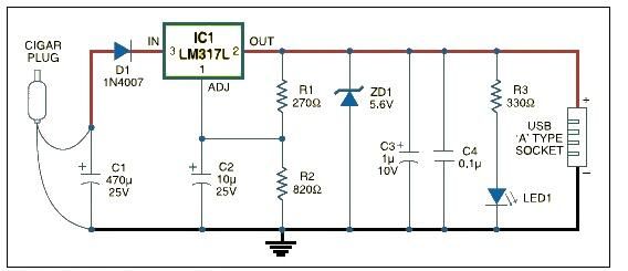
This USB car charger adapter project functions as a DC-DC power converter that effectively converts the 12V car battery voltage into a stable 5V output. It is designed to supply power from a car's cigar lighter socket to any...
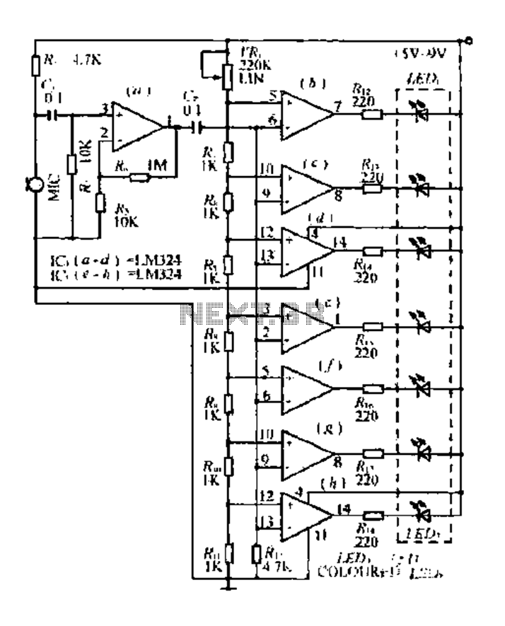
The condenser microphone pickup signal is processed by an integrated circuit (IC) where it is amplified and compared using a comparator circuit. The outputs from the comparators, designated as IC1, IC2, and IC3, provide voltage comparisons based on different...
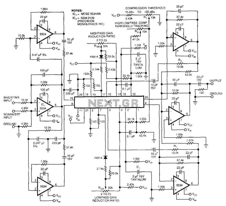
This 2-band compressor separates audio into high and low frequencies, allowing for independent adjustments of each band. Two active filters drive the two halves of a dual voltage-controlled amplifier/rectifier integrated circuit (IC). Each section features a dynamic range exceeding...
This document presents an intriguing collection of frequency dividers with division factors ranging from 2 to 10. All options are based on the 7490, which is a decade and binary counter. The frequency dividers utilizing the 7490 integrated circuit (IC)...
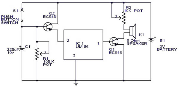
This circuit is a slight modification of a previous design. In the earlier version, the switch needed to be held down for the entire duration of the music playback. In this updated circuit, pressing the push button once charges...
Warning: include(partials/cookie-banner.php): Failed to open stream: Permission denied in /var/www/html/nextgr/view-circuit.php on line 713
Warning: include(): Failed opening 'partials/cookie-banner.php' for inclusion (include_path='.:/usr/share/php') in /var/www/html/nextgr/view-circuit.php on line 713