
usb car charger adapter circuit design
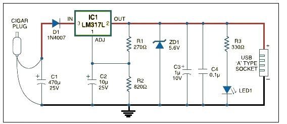
The USB car charger adapter circuit is an essential device for modern automotive applications, allowing users to charge and power their electronic gadgets while on the go. The LM317L voltage regulator is pivotal in this design, as it provides adjustable voltage output, making it suitable for various devices that operate at 5V. The input voltage from the cigar lighter socket, which typically ranges from 12V to 14.4V depending on the vehicle's electrical system, is efficiently stepped down by the LM317L.
The resistors R1 and R2 are selected based on the desired output voltage and are calculated using the formula provided in the LM317L datasheet. This ensures that the output voltage remains stable at 5V, even with fluctuations in the input voltage or load. The inclusion of the red LED (LED1) not only provides a visual indication that the charger is operational but also serves as a useful diagnostic tool for users to confirm that power is being supplied to the USB device.
Furthermore, the zener diode (ZD1) is critical for safeguarding the circuit against voltage spikes that may occur due to sudden changes in the vehicle's electrical system or external factors. It clamps the voltage to a safe level, thereby protecting the LM317L and connected devices from potential damage.
Overall, this USB car charger adapter circuit exemplifies an efficient and practical solution for powering USB devices in a vehicle, combining functionality with safety features to ensure reliable operation. The design is straightforward, making it accessible for hobbyists and professionals alike to implement in various automotive projects.This USB car charger adapter project is a DC DC power converter that safely converts the 12V car battery voltage into stable 5V. This USB car charger circuit can be used to supply power from a car cigar lighter socket to a portable device that require a 5 volts.
This circuit makes it possible to power/recharge any USB power-operated device, using in-dash board cigar lighter socket of your car. The DC supply available from the cigar lighter socket is fed to an adjustable, three-pin regulator LM317L (IC1). R1 and R2 resistors regulate the output of IC1 to steady 5V, which is available at the A` type female USB socket.
Red LED1 indicates the output status and zener diode ZD1 acts as a protector against high voltage. 🔗 External reference
Related Circuits
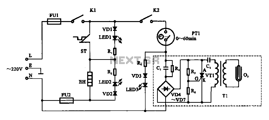
The dispenser (Aucma) temperature detection control circuit is designed to manage the temperature of the dispenser. It consists of two primary components: a heating control circuit and a fresh cabinet control circuit that provides power to an ozone generator....
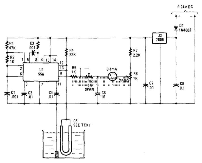
Using a capacitor sensor to detect water levels is a straightforward sensing method. This circuit employs C5, which consists of 10 to 20 inches of #22 enameled wire as one of the electrodes. The oscillator, an NE556 timer, experiences...
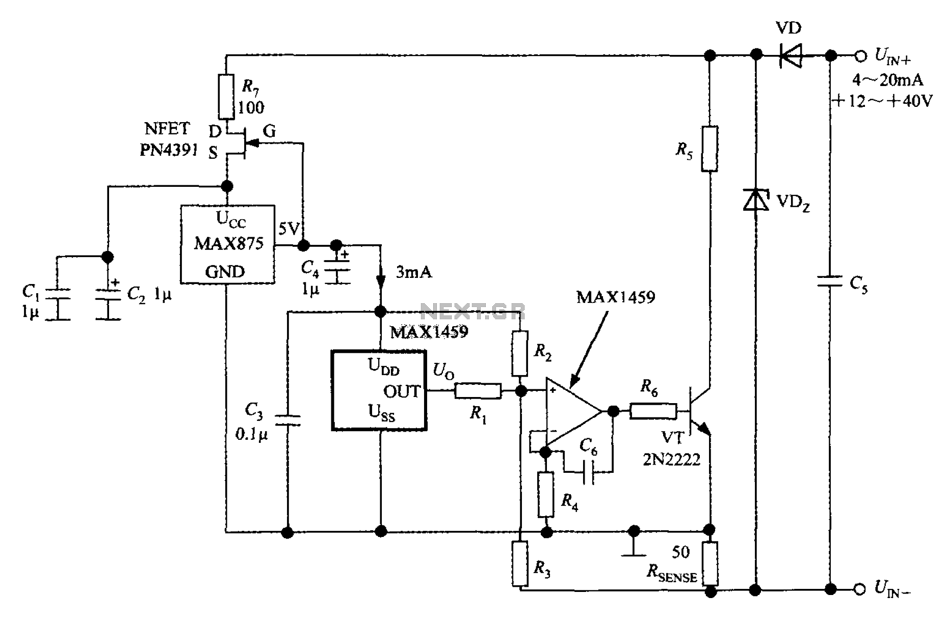
A 4 to 20 mA current transmitter circuit is implemented using the MAX1459, as illustrated in the accompanying figure. The output voltage from the programmable gain amplifier (PGA) is supplied to a spare amplifier chip, and subsequently, an external...
The preamp circuit is completely conventional, and by necessity is AC coupled throughout. The artificial earth is derived by two resistors (R1 and R2), which will set the "earth" at exactly 1/2 the supply voltage. This is nominally 13.8V...
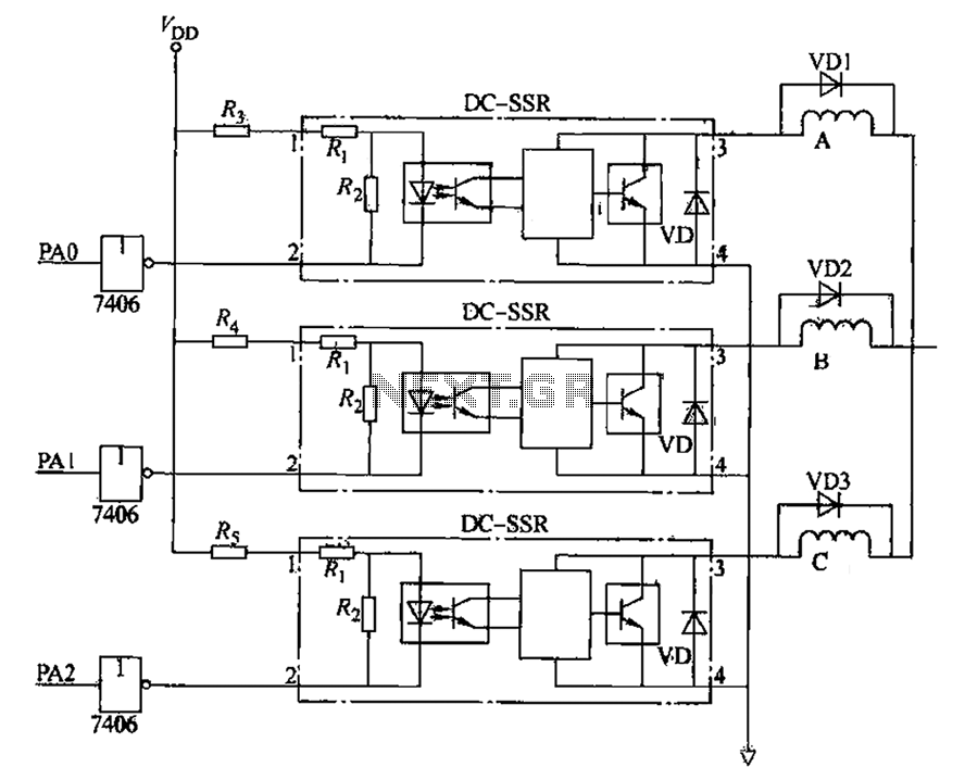
The figure illustrates that the DC Solid State Relay (SSR) in the input stage functions as an opto-isolator. When the switch output is high, the driver circuit inverts this signal to low. This process involves a light-emitting diode (LED)...
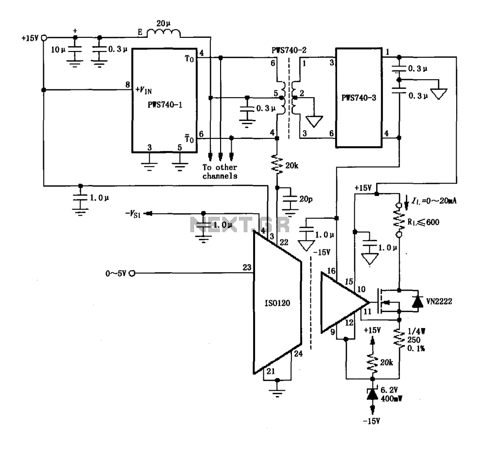
An eight-channel isolation circuit is constructed using the ISO120 and PWS740 components, designed for a 0 to 20 mA current loop. The figure illustrates only one channel, where the circuit converts a 0 to 5V input voltage into a...