
3 transistor audio amp 80 milliwatt

The circuit employs a configuration that enhances audio output by utilizing positive feedback, which is crucial for achieving higher amplitude levels. The design centers around a pair of NPN transistors, wherein the first transistor acts as a driver and the second as a power amplifier. The 470µF capacitor plays a pivotal role by storing charge, which is released to assist in the transition of the upper NPN transistor during positive output swings. The choice of a 1k load resistor connected to the speaker is intentional; it ensures that the output can effectively turn off the upper transistor when the output signal dips, thus maintaining efficient operation.
The introduction of diodes in place of the 300-ohm resistor serves to stabilize the biasing of the transistors, allowing the circuit to function efficiently across a range of supply voltages. This adjustment not only reduces distortion but also ensures that the amplifier can operate effectively even as the battery voltage decreases. The transistors selected should have sufficient current handling capabilities, with a preference for those exceeding 100mA to ensure reliable performance under load conditions.
It is essential to monitor the idle current to prevent overheating, which could lead to component failure. The output stage is designed to work with an 8-ohm speaker, which is a common impedance in audio applications, although users should be aware that power output may be less than optimal compared to a dedicated low-impedance design. The circuit's adaptability allows for a range of resistors to be used in determining the output voltage, providing flexibility based on the specific transistors chosen for the application. This design effectively balances performance and component selection, making it a viable option for small audio amplification needs.This circuit is similar to the one above but uses positive feedback to get a little more amplitude to the speaker. I copied it from a small 5 transistor radio that uses a 25 ohm speaker. In the circuit above, the load resistor for the driver transistor is tied directly to the + supply. This has a disadvantage in that as the output moves positive, the drop across the 470 ohm resistor decreases which reduces the base current to the top NPN transistor. Thus the output cannot move all the way to the + supply because there wouldn`t be any voltage across the 470 resistor and no base current to the NPN transistor.
This circuit corrects the problem somewhat and allows a larger voltage swing and probably more output power, but I don`t know how much without doing a lot of testing. The output still won`t move more than a couple volts using small transistors since the peak current won`t be more than 100mA or so into a 25 ohm load.
But it`s an improvement over the other circuit above. In this circuit, the 1K load resistor is tied to the speaker so that as the output moves negative, the voltage on the 1K resistor is reduced, which aids in turning off the top NPN transistor. When the output moves positive, the charge on the 470uF capacitor aids in turning on the top NPN transistor.
The original circuit in the radio used a 300 ohm resistor where the 2 diodes are shown but I changed the resistor to 2 diodes so the amp would operate on lower voltages with less distortion. The transistors shown 2n3053 and 2n2905 are just parts I used for the other circuit above and could be smaller types.
Most any small transistors can be used, but they should be capable of 100mA or more current. A 2N3904 or 2N3906 are probably a little small, but would work at low volume. The 2 diodes generate a fairly constant bias voltage as the battery drains and reduces crossover distortion. But you should take care to insure the idle current is around 10 to 20 milliamps with no signal and the output transistors do not get hot under load.
The circuit should work with a regular 8 ohm speaker, but the output power may be somewhat less. To optimize the operation, select a resistor where the 100K is shown to set the output voltage at 1/2 the supply voltage (4. 5 volts). This resistor might be anything from 50K to 700K depending on the gain of the transistor used where the 3904 is shown.
🔗 External reference
Related Circuits
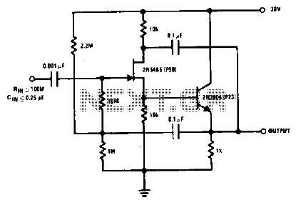
The 2N5485, which has a very low-capacity legacy, is always operated as a source follower with gate bias bootstrap. In this circuit, nothing is left to chance in reducing input capacitance. The 2N5485 is a JFET (Junction Field Effect Transistor)...
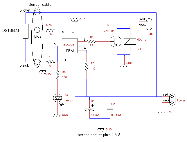
This is a fan controller designed for an audio/video cabinet. It utilizes a PICAXE 08M microcontroller and a DS18B20 temperature sensor. The fan activates at 30 degrees Celsius (approximately 86 degrees Fahrenheit) and deactivates at 28 degrees Celsius (around...
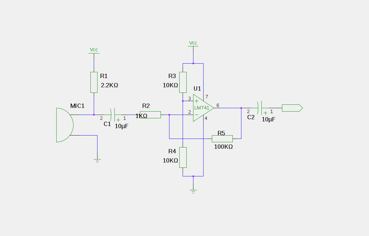
An electret microphone has been connected to an operational amplifier (op-amp), with the output directed to an Arduino microcontroller. The analog-to-digital converter (ADC) on the microcontroller converts a voltage range of 0 to 5 volts into a 10-bit number,...
This instrument is a sensitive analyzer that detects changes in frequency and the width of an acoustic signal. The brightness of the LED that activates at any given moment is proportional to the width of the signal, while the...
The circuit diagram of a guitar preamplifier is designed to accept any standard guitar pickup. This preamplifier is versatile, featuring two signal outputs. A typical configuration involves a pickup attached to the guitar headstock, where the pickup device consists...
The mixer is the common "virtual earth" mixing amplifier, and there is nothing special about it. Note that it is inverting, which complements the tone controls (also inverting) so the absolute signal polarity is maintained. As shown, the mixer...