
Audio amplifier output relay delay
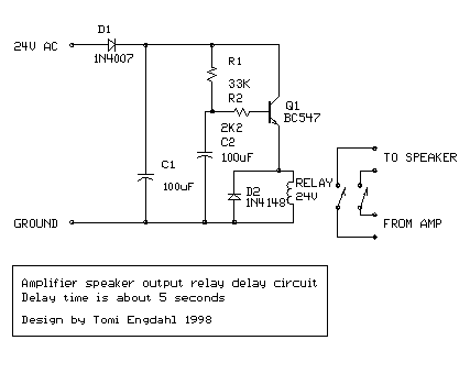
The circuit operates by utilizing a combination of capacitors, resistors, diodes, and a transistor to create a time delay mechanism for the relay. Initially, when power is applied to the circuit, C1 charges quickly, providing an immediate supply of energy to the circuit. The slower charging of C2 through R1 is the key to establishing the delay. The resistor R1 acts to limit the current flowing into C2, thus controlling the charging rate and, consequently, the timing of the relay activation.
The transistor Q1 functions as a switch that is controlled by the voltage across C2. As C2 charges, the voltage at the base of Q1 rises, allowing it to conduct when the threshold voltage is reached. This conduction activates the relay, which is responsible for connecting the speaker output to the amplifier. The relay's coil, rated for 24V DC, is selected to ensure reliable operation, and its resistance ensures that it draws a manageable current from the circuit.
To ensure that the speakers are disconnected promptly when power is removed, C1 discharges quickly, while C2, charged through R2, also discharges rapidly. This design minimizes the risk of audible pops or thumps that can occur when power is interrupted. The choice of components, particularly the electrolytic capacitors, plays a significant role in the performance of the circuit. Using capacitors with tighter tolerances may improve the accuracy of the delay, while larger capacitor values can be employed for longer delays.
Overall, this simple relay control circuit is effective for audio applications where speaker protection during power transitions is desired. Its straightforward design allows for easy modification and adaptation to various electronic projects requiring similar functionality.This is a simple circuit which I built to one of my audio amplifier projects to control the speaker output relay. The purpose of this circuit is to control the relay which turns on the speaker output relay in the audio amplifier.
The idea of the circuit is wait around 5 seconds ofter the power up until the spakers are switched to the amplfier outp ut to avoid annoying "thump" sound from the speakers. Another feeature of this circuit is that is disconnects the speaker immdiatly when the power in the amplifier is cut off, so avoinding sometimes nasty sounds when you turn the equipments off. C1 100 uF 40V electrolytic C2 100 uF 40V electrolytic D1 1N4007 D2 1N4148 Q1 BC547 R1 33 kohm 0. 25W R2 2. 2 kohm 0. 25W RELAY 24V DC relay, coil resistance >300 ohm Then power is applied to the power input of the circuit, the positive phase of AC voltage charges C1.
Then C2 starts to charge slowly through R1. When the voltage in C2 rises, the emitter output voltage of Q1 rises tigether with voltage on C2. When the output voltage of Q2 is high enough (typically around 16. 20V) the relay goes to on state and the relay witches connect the speakers to the amplifier output. It takes typically around 5 seconds after power up until the relay starts to condict (at absolute time depends on the size of C2, relay voltage and circuit input voltage). When the power is switched off, C1 will loose it`s energu quite quicly. Also C2 will be charged quite quicly through R2. In less than 0. 5 seconds the speakers are disconnected from the amplifier output. This circuit is not the most accurate and elegant design, but it has worked nicely in my small homebuilt PA amplifier.
This circuit can be also used in many other applications where a turn on delay of few seconds is needed. The delay time can be increased by using bigger C2 and decreased by using a smaller C2 value. Note that the delay is not very accurate because of simplicity of this circuit and large tolerance of typical electrolytic capacitors (can be -20%.
+50% in some capcitors). 🔗 External reference
Related Circuits
This circuit enables the display of an ECG signal on an oscilloscope. Operational amplifiers IC1a, IC1b, and IC1d create an instrumentation amplifier with a gain of 201. IC1c amplifies the common-mode signal by a factor of 31 and supplies...
The clock frequency ranges from 5 kHz to 50 kHz, with a delay time adjustable between 51.2 ms and 5.12 ms. The clock frequency must be at least double the highest audio frequency. The described circuit operates within a clock...
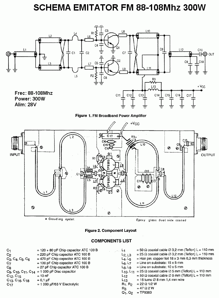
This is a 300 W RF amplifier designed for FM transmission, capable of operating within the frequency range of 88 to 108 MHz. The amplifier utilizes two TP9383 transistors, enabling it to deliver up to 300 W of output...
More: The provided input lacks specific details or context regarding an electronic circuit or schematic. To create a comprehensive electronic schematic description, it is essential to include key components, their interconnections, and the overall functionality of the...
The TDA7052 is a mono output amplifier housed in an 8-pin Dual In-line Package (DIP). This device is specifically designed for use in battery-operated portable audio applications. Key features of the TDA7052 include the absence of external components, elimination...
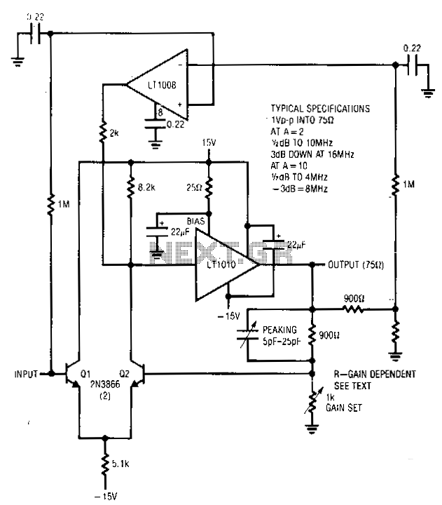
This amplifier operates across a broad range of gains, typically from 1 to 10. It integrates the LT1010 with a fast discrete stage and an LT1008-based destabilizing loop. Transistors Q1 and Q2 create a differential stage that converts to...
Warning: include(partials/cookie-banner.php): Failed to open stream: Permission denied in /var/www/html/nextgr/view-circuit.php on line 713
Warning: include(): Failed opening 'partials/cookie-banner.php' for inclusion (include_path='.:/usr/share/php') in /var/www/html/nextgr/view-circuit.php on line 713