
ECG Amplifier By TLC274

This ECG display circuit utilizes a robust design to ensure accurate signal processing and safety during use. The instrumentation amplifier configuration, consisting of multiple operational amplifiers, is key to achieving high gain while maintaining stability and noise rejection. The gain of 201 is critical for amplifying the weak ECG signals generated by the heart, which typically range in the millivolt level.
The common-mode signal amplification by IC1c is essential for establishing a reference level for the ECG measurements. By applying this common-mode signal to the right leg, the circuit effectively balances the potential differences that may arise due to body movement or external interference, thus ensuring that the ECG signal remains within the operational range of the instrumentation amplifier.
The inclusion of diodes D1 to D4 and resistors R1 and R5 serves as a protective measure against high-voltage transients, which could damage sensitive components in the circuit. This is particularly important in biomedical applications, where the risk of electrostatic discharge (ESD) is significant.
The adjustment of the common-mode rejection ratio using potentiometer P1 allows for fine-tuning of the circuit to optimize performance in various environments. This procedure is vital for ensuring that the ECG readings are as accurate as possible, eliminating any unwanted noise that could obscure the signal.
The design emphasizes the importance of electrode placement and contact quality. The method of wrapping copper wires around fingers and the leg demonstrates a practical approach to obtaining reliable ECG signals without the need for specialized electrodes, highlighting the circuit's versatility.
With a low current consumption of 2mA, this circuit is designed for efficiency, allowing for prolonged use without frequent battery replacements. The explicit warning against connecting the circuit to mains power underscores the critical safety measures necessary when interfacing with human subjects, ensuring that the circuit remains safe for both the user and the patient.This circuit allows an ECG signal to be displayed on an oscilloscope. Opamps IC1a, b and d form an instrumentation amplifier with a gain of 201. IC1c amplifies the common-mode signal by a factor of 31, and supplies this signal to the right leg. The first consequence of this is that the body is brought to a defined common-mode level, so that the si gnal will not lie outside the range of the instrumentation amplifier. The second consequence is that negative feedback is applied to the common-mode signal, so that the amplitude of this (undesired) signal is reduced even further. Diodes D1 through D4, along with resistors R1 and R5, are added to the circuit to protect the inputs against damage from excessive electrostatic charges.
The CMRR (common-mode rejection ratio) of the instrumentation amplifier can be set using P1. To make this adjustment, connect both inputs of the instrumentation amplifier together, and then connect a 100mV, 50Hz AC signal between the connected inputs and earth. Measure the output signal using an oscilloscope, and adjust P1 to minimize the level of the output signal.
It is important that the electrodes make very good contact with the skin. In our test measurements, winding three uninsulated copper wires several times around the index fingers (and the right leg) proved to be sufficient to provide a good signal. The amplitude of the ECG signal measured with this arrangement was 200mV. The current consumption of this circuit is only 2mA, so the batteries should last a long time. This circuit must never be connected to a mains-operated power supply, in consideration of safety precautions that are necessary when making this sort of measurement on the human body.
🔗 External reference
Related Circuits
Since the 1970s, a remarkable era in technology, amplifiers have been available in integrated chip form, eliminating the need to construct them from numerous discrete transistors. This video provides an overview of operational amplifiers (op amps) and includes an...
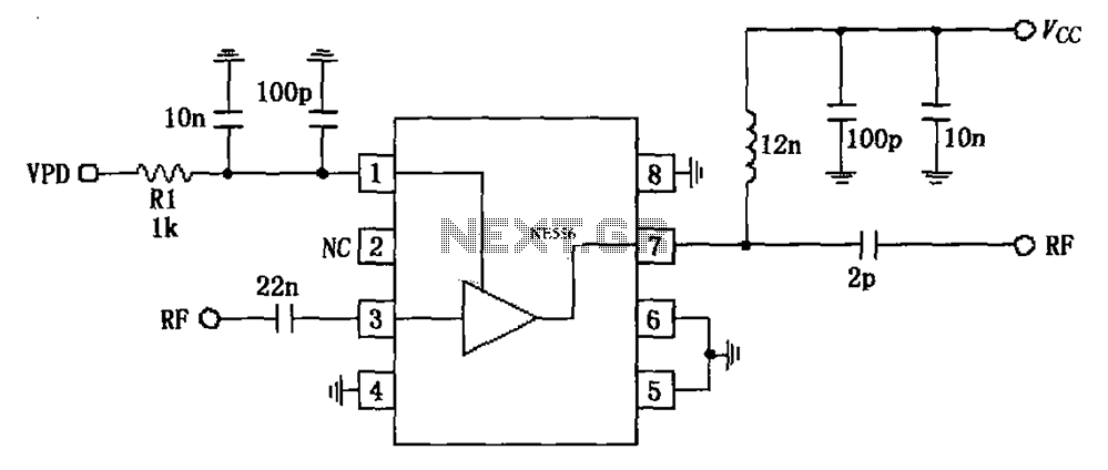
The circuit is based on an 880 MHz RF2347 low noise amplifier application. The radio frequency (RF) signal enters through input pin 3, and after amplification, the output is available at pin 7. The amplifier is directly coupled to...

Here is an amplifier circuit based on the BUZ11, which can be replaced by an IRFZ34N, and an ECC83 can be used instead of the ECC88. In this case, the anode voltage should be reduced slightly to 155 V....

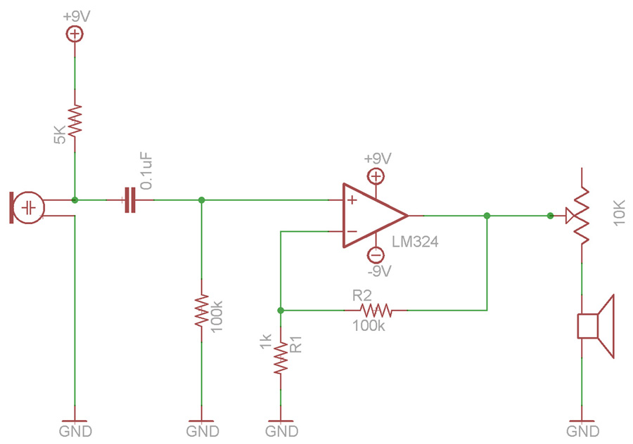
The circuit is fundamentally based on a well-tested simple microphone preamplifier design. A prototype of this circuit has been constructed and has demonstrated effective performance. The Sound Blaster soundcard series (SB16, SB32, AWE32, and AWE64) features a microphone input...

The circuit diagram presented is for a compact mini audio power amplifier that operates with a DC supply voltage ranging from 4.5 volts to a maximum of 18 volts. This amplifier utilizes the TDA1015 integrated circuit, produced by NXP...
Can be directly connected to CD players, tuners and tape recorders. Tested with several headphone models of different impedance: 32, 100, 245, 300, 600 & 2000 Ohms. Schematic shows left channel only. B1, SW1, J1 & C3 are common...