
audio bandpass filter
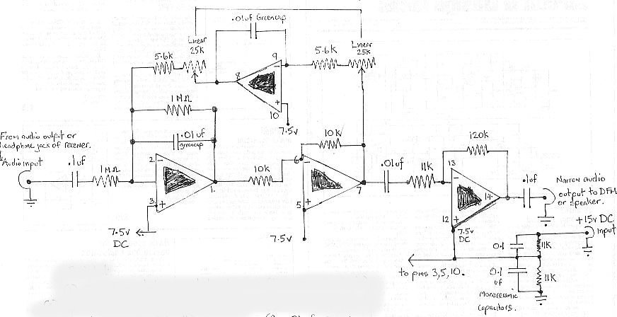
The audio bandpass filter design focuses on effectively amplifying and filtering specific frequency ranges to enhance the performance of various audio and video applications. The filter's architecture combines both low-pass and high-pass filtering capabilities, allowing for selective frequency transmission while attenuating unwanted signals outside the designated bandwidth. The filter's narrow bandwidth of approximately 20 Hz is particularly advantageous for applications requiring precise frequency discrimination, such as in the reception of weak AM video carriers, where signal clarity is crucial.
The integration of a digital frequency audio multimeter (DFM) or audio monitor speaker at the output stage facilitates real-time monitoring and adjustment of the filter's performance. This enables users to optimize the filter settings to achieve the best possible signal quality. The option to utilize software tools like Spectrum Lab provides additional flexibility for visualizing the frequency spectrum, aiding in the identification and separation of closely spaced video carriers.
The tuning mechanism of the filter, utilizing a 50 kΩ potentiometer, offers a broad adjustment range, allowing for precise resonance tuning within the specified frequency limits. The addition of a fine-tuning potentiometer further enhances the filter's versatility, making it suitable for various receivers with differing tuning capabilities. The transition from the LM348 to the LM6134BIN operational amplifier marks a significant improvement in the filter's high-frequency response, ensuring that the filter can handle a wide spectrum of audio frequencies effectively.
In summary, this audio bandpass filter serves as a critical component for applications involving weak AM TV video carriers, providing both amplification and filtering capabilities while maintaining a narrow bandwidth for optimal signal processing. Its design allows for user customization and adaptability, making it a valuable tool for audio and video signal analysis.The audio bandpass filter described is useful for amplification and filtering weak AM TV video carriers. For example, a DFM (digital frequency audio multimeter) may have insufficient input sensitivity for measuring extremely weak SSB TV video audio signals.
By using the 20 Hz filter to peak the wanted carrier, the DFM will display the carrier freq uency. Another possible application for this filter is increased amplification and reduced bandwidth of weak BCB heterodyne AM carriers. The filter is also very useful for separating video carriers that are in close proximity of each other.
By definition, a bandpass filter is usually a low-pass and high-pass filter in series, allowing only a certain range of frequencies through. Because the cut-off frequencies are close to one another, the effect will be similar to that of a peaking filter.
The bandwidth of the filter, when peaked is approximately 20 Hz. This is much narrower than the typical 2. 4 KHz SSB bandwidth of most communications receivers. The advantage of this filter is a constant 20 Hz bandwidth, regardless of the resonant frequency, when peaked between 400-4000 Hz. The audio line-out or headphone output from a VHF/UHF scanning or communications receiver is connected to the input of the bandpass filter.
The output of the bandpass filter is connected to a digital frequency meter (DFM), and/or audio monitor speaker. A monitor speaker is used when tweaking the filter`s resonant frequency. If a DFM is not used, a PC program, such as Spectrum Lab could be used for spectral display of TV video carriers on a computer screen.
The tuning range of the filter is from ~ 400 Hz to 4 KHz, when using a 50 KHz potentiometer. The writer typically tunes the filter to resonate around ~ 1000-1300 Hz. This frequency range corresponds to the maximum output level of 2. 4 KHz USB mode. A 10K fine tuning potentiometer has also been added (not shown on the schematic). This can be included in series with the main 50K pot. I did this on my filter, and the centre of the tuning range moved from 300 Hz to 1000 Hz and improved the bandspread by a factor of about 4 times up to 2 kHz. A fine tune pot is useful for use with receivers that have 100 Hz minimum tuning steps, for example, Icom R7000/7100/8500, etc.
Initially, a LM348 op-amp was used in the circut. Although this worked ok, it was found that by replacing the LM348 with a LM6134BIN IC, improved high frequency response was obtained. 🔗 External reference
Related Circuits
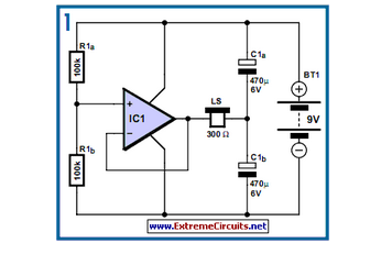
The circuit is designed to establish a monitoring and surveillance system for a remote location, functioning as a room monitor or baby alarm. The proposed circuit for the monitoring and surveillance system incorporates various electronic components to ensure reliable operation...
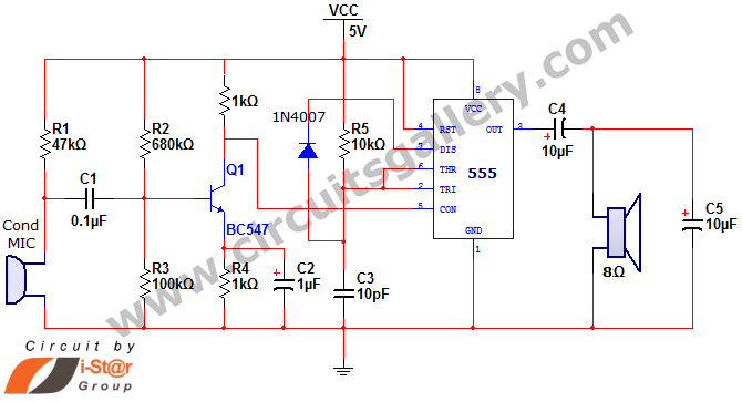
This document discusses a simple project utilizing the 555 timer IC. The 555 timer IC can be configured as an audio amplifier using an astable multivibrator configuration. It performs pulse width modulation (PWM) on an audio signal. The current...
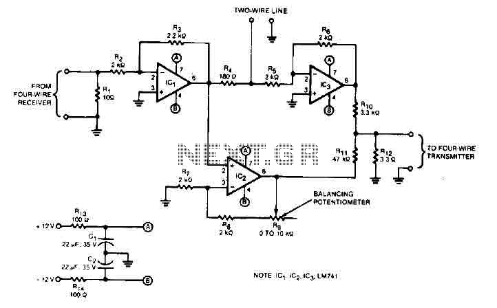
This audio converter circuit maintains 40 dB of isolation between the two halves of entry and exit of a four-line system while allowing a line connection between the two systems. A balancing potentiometer, R, adjusts the gain of the...
Designs for audio amplifiers with DC coupling to the load are not commonly seen today, despite their clear benefits. One advantage... Audio amplifiers utilizing DC coupling to the load present several notable advantages in specific applications. DC coupling allows for...
The TA8210AH integrated circuit (IC) is designed for use as an audio power amplifier in car audio systems. Typically, car audio setups include subwoofers and woofers, as the confined space of a vehicle does not require excessively high sound...
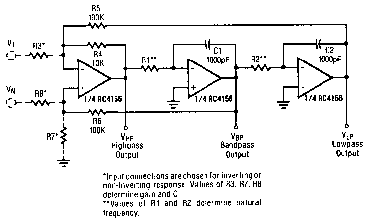
A generalized circuit diagram of the two-pole state-variable active filter is presented. This state-variable filter can be configured as either inverting or non-inverting and is capable of providing three simultaneous outputs: low-pass, bandpass, and high-pass. By incorporating an additional...
Warning: include(partials/cookie-banner.php): Failed to open stream: Permission denied in /var/www/html/nextgr/view-circuit.php on line 713
Warning: include(): Failed opening 'partials/cookie-banner.php' for inclusion (include_path='.:/usr/share/php') in /var/www/html/nextgr/view-circuit.php on line 713