
Audio Booster

The audio booster circuit is designed to enhance sound quality by amplifying audio signals while maintaining clarity and fidelity. The linear potentiometer R5 serves as a volume control and on/off switch, allowing for easy adjustment of the audio output level. The choice of capacitor C1 is critical; its value influences the frequency response of the amplifier. A capacitor value within the specified range ensures that the amplifier operates efficiently at the desired frequencies, particularly in the context of the crossover filter.
The amplifier's configuration is optimized for a total output of 20 watts, split evenly across two channels. Each channel drives a tweeter and a woofer, which are essential for reproducing a full range of audio frequencies. The active crossover filter at 2 kHz ensures that high frequencies are directed to the tweeter and low frequencies to the woofer, preventing distortion and enhancing sound quality.
The loudspeakers used in this circuit must be rated for 10 watts of power and have an impedance of 4 ohms, which is a common specification for consumer audio equipment. This impedance allows the amplifier to deliver sufficient power without overloading the speakers. The supply voltage range of 12 volts and above provides flexibility in powering the circuit, accommodating various power supply options while ensuring optimal performance. Overall, this audio booster circuit is well-suited for applications requiring enhanced audio output with precise control over sound quality.Booster for audio circuit diagram. Potentiometer R5 of 100K is a linear type with an on/off switch attached. The value of C1 may need to be between 0. 05 µF and 0. 1 µF (47nF/100nF). Experiment with the value for best performance. This is a20 watts audio amplifieris suppliedwith a voltage14. 4volts, givinga total power of20wattsinto twodifferent chann els, each of whichis connectedto thetweeteranda woofer. This amplifier isthereforeequipped with an active CROSSOVERfilterwithacrossoverfrequencyof 2KHz. Eachloudspeakermust supporta power of 10wattsandhaveanimpedanceof 4 ohms. The supply voltagecan bebetween12and up. 🔗 External reference
Related Circuits
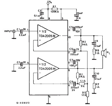
TDA2005 car audio amplifier circuit diagram electronic project using few external electronic parts The TDA2005 is a robust integrated circuit designed for audio amplification in automotive applications. This circuit diagram outlines a project for a car audio amplifier that utilizes...
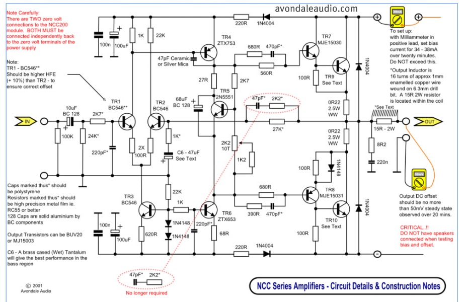
This is a simple circuit that features high-performance power amplifiers. The power amplifier is available as a PCB, along with a complete list of components. The described circuit utilizes high-performance power amplifiers, which are essential for applications requiring significant signal...
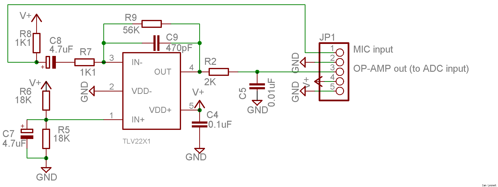
This project utilizes a small, common electret microphone to convert audio into an electrical signal. These inexpensive microphones are typically found in most PC headsets. The output from the microphone must be amplified and zeroed before it can be...

A gyrator is a circuit that utilizes active devices and transistors to emulate an inductor. In this instance, the gyrator comprises a transistor in conjunction with resistors R1, R3, and capacitor C2. Alternatively, a unity gain operational amplifier could...
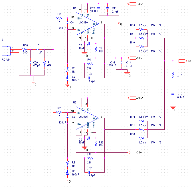
This audio amplifier design utilizes two LM3886 chips per channel in a parallel configuration, based on the PA100 parallel amplifier detailed in National Semiconductor's application note AN1192. The amplifier can deliver approximately 50W into an 8-ohm speaker and 100W...
Here a simple design for an attractive tone. They operate on a passive principle, ie without amplification. The circuit only weakened and therefore require no power. As can be seen, the circuit is built with two T-filters in the...