
audio graphic equalizer circuit

The gyrator circuit is a crucial element in analog signal processing, particularly in applications where inductance is required but physical inductors are impractical or undesirable due to size, cost, or performance issues. The active components, such as transistors or operational amplifiers, allow the circuit to simulate inductive behavior effectively.
In the described configuration, the transistor interacts with resistors R1 and R3, forming a feedback loop that establishes the necessary phase shift to emulate an inductor's behavior. The values of R1 and R3, along with the capacitance of C2, are critical in determining the circuit's performance characteristics, such as the center frequency and quality factor.
The center frequency (f) is a pivotal parameter, defined by the circuit's reactive components, and is calculated using the associated formula. This frequency indicates where the circuit will exhibit its peak response. The quality factor (Q) reflects the selectivity and bandwidth of the bandpass response, with a higher Q indicating a narrower bandwidth and sharper resonance.
The impedance presented by the gyrator circuit is a combination of resistive, capacitive, and inductive elements. The resistive component arises from the resistors, while the capacitive contribution comes from capacitor C1. The inductive term, which is the key feature of the gyrator, arises from the active device's operation, effectively allowing the circuit to behave as if it includes an inductor.
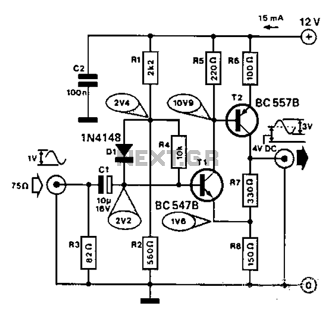
This configuration can be particularly advantageous in filter design, oscillators, and other applications where inductive elements are needed without the drawbacks of physical inductors. The gyrator's ability to simulate inductance through active components allows for greater flexibility and integration in modern electronic designs.A gyrator is a circuit using active devices and transistors to simulate an inductor. In this case the gyrator is the transistor acting with R1, R3 and C2. It could just as easily be a unity gain op-amp (which gives superior performance). The circuit includes three formulae: one which gives f, the centre frequency of the band. The second shows how the Q is related to the capacitor ratio. The third shows the impedance presented by the circuit. Note that this includes 3 terms, the first purely resistive, the second is the capacitive contribution from C1 and the third is an inductive term from the gyrator. 🔗 External reference
Related Circuits
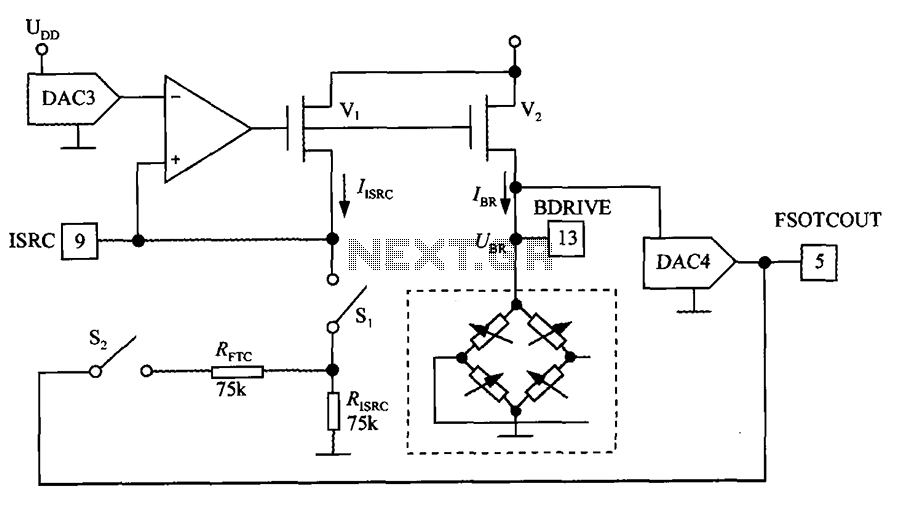
The excitation circuit for the digital pressure signal conditioner MAX1458 is illustrated. The output DAC3 is utilized to adjust the sensor excitation current (IBR), enabling full-scale fine calibration. The reference current (IISRC) is determined by the resistor RISRC and...
An LED flasher circuit can be constructed using a 555 integrated circuit (IC). The use of the 555 IC allows for greater flexibility in adjusting the flashing rate of the LED. This LED flasher circuit is similar to other...
This circuit is designed for precise measurement of temperature in degrees Celsius. It features a transmitter section that converts the output voltage from the temperature sensor, which is proportional to the measured temperature, into a frequency signal. This frequency...
This is a 25 Watt basic power amplifier designed to be relatively easy to build at a reasonable cost. It offers better performance than standard STK module amplifiers commonly found in mass-market stereo receivers. The original design was created...
Commonly used for cameras or computers with black and white television connections, the amplifier has a gain of 3 and a bandwidth of 10 MHz. The described circuit is an amplifier designed for applications involving cameras or computers that interface...
This circuit illustrates the high and mid-frequency sections of a car radio. The medium wave band I operates within the frequency range of 520 to 950 kHz, while Poland II operates between 900 and 1640 kHz. The circuit employs...
Warning: include(partials/cookie-banner.php): Failed to open stream: Permission denied in /var/www/html/nextgr/view-circuit.php on line 713
Warning: include(): Failed opening 'partials/cookie-banner.php' for inclusion (include_path='.:/usr/share/php') in /var/www/html/nextgr/view-circuit.php on line 713