
Audio
The non-inverting amplifier circuit is fundamental in audio applications, particularly for amplifying signals from microphones. In this configuration, the microphone acts as a variable resistor, converting sound waves into an electrical signal. The non-inverting amplifier designed for this purpose utilizes an operational amplifier (op-amp), specifically the TL081, known for its low noise and high input impedance, making it suitable for audio applications.
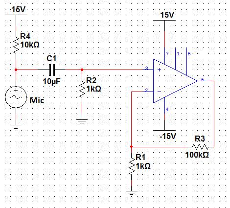
The primary components of the circuit include the microphone, biasing resistors, and capacitors. Resistor R4 is crucial for providing the necessary bias current to the electret microphone, enabling it to function correctly. Capacitor C1 serves a dual purpose: it blocks any DC component from the microphone while allowing the AC signal (the audio signal) to pass through to the op-amp. This ensures that only the desired audio frequencies are amplified.
The gain of the amplifier is set by the configuration of the resistors, particularly R2, which also plays a role in creating a high-pass filter with C1. This filter is essential for removing low-frequency noise and ensuring that the amplifier operates effectively within the desired frequency range. The calculated cutoff frequency of the high-pass filter can be determined using the formula \( f_c = \frac{1}{2\pi R_2 C_1} \).
The performance of the amplifier circuit can be analyzed using simulation software, which predicts a gain of 40 dB and establishes the bandwidth limits of the amplifier. The gain-bandwidth product is a critical parameter that helps in understanding the frequency response of the amplifier, indicating that as gain increases, the bandwidth decreases.
For practical testing, the Bode analyzer is employed to visualize the frequency response of the circuit, confirming that the amplifier operates within the expected parameters. The inclusion of the buffer circuit is a significant enhancement, allowing the op-amp to drive low-impedance loads, such as speakers, without compromising the signal integrity from the microphone.
Overall, this lab demonstrates the essential principles of non-inverting amplifiers and their applications in audio signal processing, providing a solid foundation for further exploration in electronic circuit design.This lab will demonstrate the theory and operation of non-inverting amplifiers as well as their practical application to amplify the signal of a microphone. We will construct a non-inverting amplifier to increase the output signal of a microphone, and use this circuit to measure the performance of a loudspeaker Electret capsule microphones are ver
y popular due to their decent performance and low price. The simplest way to imagine the microphone`s operation is to view it as a resistor whose value varies when a sound wave hits it. If a bias current flows through this varying resistance, it will create a small voltage that must be amplified for useable purposes.
Build the circuit in Figure 4 shown below. In the above circuit, R4 provides the bias current for the microphone. Capacitor C1 prevents the DC voltage across the microphone from being amplified, while allowing the AC signal to pass to the amplifier. Resistor R2 provides a DC bias current path for the TL081 but also creates a high-pass filter with C1, whose cut off frequency can be determined as: The simulation shows that the circuit has a gain of 40 dB as predicted and its low frequency roll-off occurs around 15.
9 Hz. The upper frequency roll-off is created by the bandwidth of the opamp itself. For small signals, the easiest method to predict the bandwidth of the amplifier is to use the gain/bandwidth product (GBW) specified by the manufacturer. The TL081 has a GBW of 3 MHZ, by dividing this number by our gain of 101, we can predict the 30 kHz bandwidth of the amplifier seen in the simulation.
The Bode application included with the myDAQ can be used to verify the operation of the circuit once it`s built. Be sure to install the capacitor with polarity in the correct orientation and care should be taken when inserting the microphone into the breadboard.
To test the circuit with the bode analyzer, wire analog input 1 [AI 1+] to pin 6 of the op-amp. Wire analog input 0 [AI 0+] and analog output [AO 0 ] to the positive terminal of the 10 µF capacitor. Connect ground to the negative input terminals [AI 0-] and [AI 1-]. Both Figures 6 and 7 use the inputs and outputs listed above. However, Figure 7`s input is controlled by the function generator set to a Sine output at 1k Hz and 0.
02 Vpp. The non-inverting amplifier constructed in the previous section makes it much easier to interface the microphone to the myDAQ. Now the microphone can be used for real-world measurements and recording. In order to drive the included speaker with the myDAQ, a buffer circuit needs to be constructed. By removing the feedback resistors from the non-inverting amplifier circuit and connecting the output of the opamp directly to the inverting input, the circuit`s gain is now reduced to 1.
This means that the voltage at the output of the opamp will match the voltage at the input. You may be wondering what the benefit of the circuit is if it doesn`t provide any gain to the signal The advantage of a buffer is that it provides the necessary current to drive a low impedance load while still presenting a high-impedance load to the source. Notice in the above schematic that the analog output of the myDAQ does not provide current to the 150 Ohm speaker, the opamp does.
The impedance seen by the analog output is the value of R5, 10k Ohms in this case. Build the circuit shown above in Figure 8. A frequency response of the speaker/microphone circuit can be obtained by first connecting analog output 0 [AO 0] and analog input 0 [AI 0+] to the input of the speaker`s buffer circuit. Next connect analog input 1 [AI 1+] to pin 6 of the microphone circuit and ground the two negative input terminals [AI 0-] and [AI 1-].
Open the Bode SFP like in the previous exercises and run it with the settings shown in Figure 9. The Dynamic Signal Analyzer (DSA) can be used to view the harmonic content of the speaker`s output. To do this, open the DSA from the ins 🔗 External reference
Related Circuits
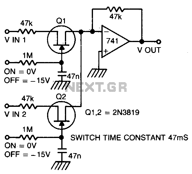
Two or more signals can be switched and/or mixed without annoying clicks by using FETs and a low input-impedance op amp circuit. The circuit design utilizes Field Effect Transistors (FETs) to facilitate the switching and mixing of multiple signals while...
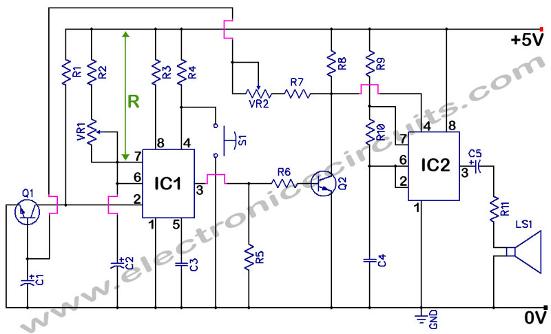
555 Timer with Audio Alarm Circuit. This circuit serves as a straightforward electronic timer equipped with an audio alarm feature. The 555 timer is a versatile integrated circuit widely used in various timer, delay, pulse generation, and oscillator applications. In...
TIP141 is an NPN silicon power Darlington transistor designed for complementary use with TIP145, TIP146, and TIP147. It can handle up to 125 W at a case temperature of 25 °C, with a continuous collector current of 10 A...
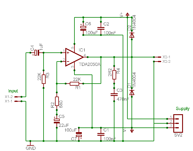
A careful examination of the amplifier photos reveals that the heatsink on the HY60 near-clone built using the TDA2050A is slightly shorter than that of the original HY60s. This unit is positioned at the rear of the amplifier, creating...
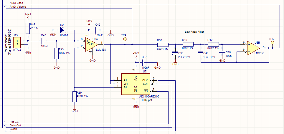
This circuit employs a digital potentiometer to enable the microcontroller to automatically adjust the circuit's gain according to the ambient audio volume. However, a standard potentiometer can be used if automatic adjustment is unnecessary. The low-pass filter design is...

This audio mixer circuit utilizes an LM3900 integrated circuit, although it is not a professional DJ mixer. The IC contains four integrated Norton amplifiers, which have the advantage of operating with a single power supply. The amplifier circuit is...