
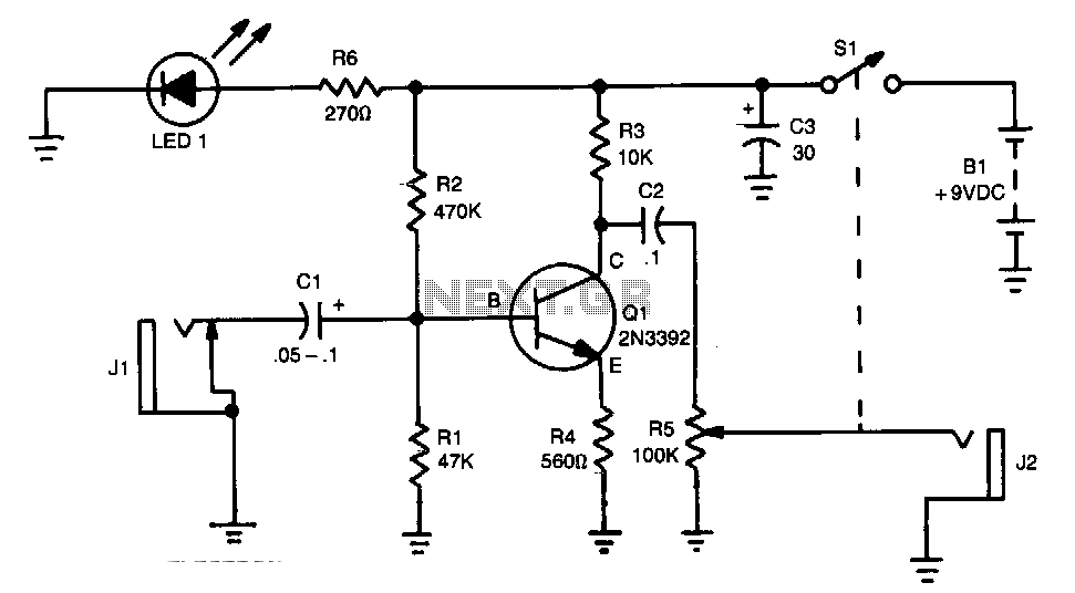
Silent audio switching-mixing

The circuit design utilizes Field Effect Transistors (FETs) to facilitate the switching and mixing of multiple signals while ensuring a smooth transition without audible clicks. FETs are favored in this application due to their high input impedance and low output capacitance, which significantly reduce the risk of signal distortion during switching events.
In this configuration, a low input-impedance operational amplifier (op amp) is employed to buffer the signals. The op amp serves to prevent loading effects that could arise from connecting multiple sources directly to the FETs. By maintaining a low input impedance, the op amp allows for effective signal processing without altering the characteristics of the original signals.
The switching mechanism can be implemented using a combination of n-channel and p-channel FETs arranged in a complementary configuration. This arrangement allows for bidirectional signal flow and enhances the circuit's versatility. Control signals applied to the gates of the FETs determine which signals are routed to the output, enabling seamless transitions between inputs.
To further minimize clicking artifacts, the circuit may incorporate additional features such as soft switching techniques or signal ramping. These methods gradually change the gate voltage of the FETs, allowing for smoother transitions and reducing the likelihood of abrupt changes in signal levels.
Overall, this circuit design presents an effective solution for mixing and switching multiple audio or signal sources in applications where signal integrity and sound quality are paramount. The careful selection of components and circuit topology ensures reliable performance while maintaining the desired signal characteristics.Two or more signals can be switched and/or mixed without annoyingclicks by using FETs and a low input-impedance op amp circuit.
Related Circuits

Proper grounding is essential for eliminating hum and ground loops. The ground connections for J1, P1, C2, C3, and C4 should all be connected to the same point. Additionally, connect C9 to the output ground. In electronic circuits, grounding serves...

This is a high-fidelity, high-quality audio amplifier circuit diagram. A pre-amplifier is not required. Component list: R1, R4 = 47K 1/4W resistors; R2 = 4.7K 1/4W resistor; R3 = 1.5K 1/4W resistor; R5 = 390Ω 1/4W resistor; R6 =...
The amplifier's gain is nominally 20 dB. Its frequency response is primarily influenced by the values of a few components, mainly C1 and R1. The values in the schematic diagram yield a response of ±3.0 dB from approximately 120...
Parts List The circuit consists of a preamplifier, tone controls, and a regulated DC power supply, providing a power output of 18 Watts for an 8 Ohm load. The circuit design includes three main components: a preamplifier, tone control circuitry,...
The LM1875 is a monolithic audio amplifier that provides very low distortion and high-quality performance for audio amplifier projects. The LM1875 delivers 20 watts into loads of 4 Ohms or 8 Ohms. The LM1875 audio amplifier is designed for applications...
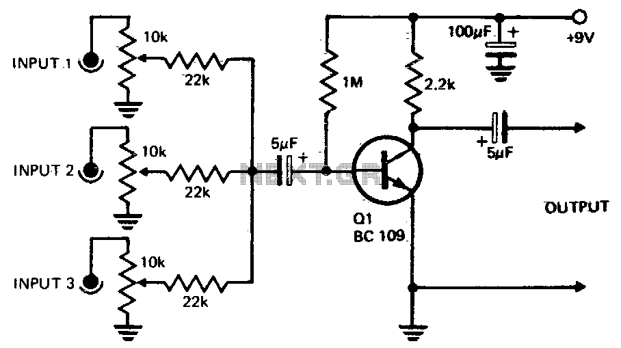
Three or more inputs with individual level controls feed into the base of Q1, which provides a voltage gain of 20. The circuit design involves a transistor amplifier configuration where three or more input signals are managed through individual level...