230V Flasher Circuit diagram

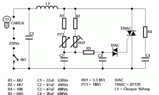
This circuit operates with 230V and can be used to decorate parties. It features a DIAC ER 900 and a TRIAC BTW 11-400.
The circuit utilizes a DIAC (Diode for Alternating Current) and a TRIAC (Triode for Alternating Current) to control the power delivery to decorative lighting or other devices. The DIAC ER 900 is designed to trigger at a specific voltage, allowing it to switch on when the voltage across it exceeds its breakdown voltage. Once triggered, the DIAC allows current to flow through the TRIAC, which then controls the power to the load.
The TRIAC BTW 11-400 is a bidirectional device that can conduct current in both directions when triggered. It is rated for a maximum current of 11A and a maximum voltage of 400V, making it suitable for handling typical household lighting loads. The combination of the DIAC and TRIAC allows for effective phase control, enabling dimming capabilities for incandescent bulbs or controlling the brightness of LED lights.
To implement this circuit, a suitable trigger circuit must be designed to provide the necessary gate current to the TRIAC. This can be accomplished using resistors and capacitors to form an RC timing circuit, which will determine the phase angle at which the TRIAC is turned on during each AC cycle. The circuit should also include appropriate safety measures, such as fuses or circuit breakers, to protect against overload conditions.
In summary, this circuit is a practical solution for creating decorative lighting effects at 230V, utilizing the reliable operation of the DIAC ER 900 and TRIAC BTW 11-400 for efficient power control.This circuit operates with 230v. you can use this circuit to decorate your parties. I think this will be a wonderful circuit to you all. Here DIAC ER 900 and Triac BTW 11-400. 🔗 External reference
Warning: include(partials/cookie-banner.php): Failed to open stream: Permission denied in /var/www/html/nextgr/view-circuit.php on line 713
Warning: include(): Failed opening 'partials/cookie-banner.php' for inclusion (include_path='.:/usr/share/php') in /var/www/html/nextgr/view-circuit.php on line 713
