
Telephone control automatic lighting circuit 1
The automatic lighting control circuit operates based on the principles of telephone line signaling. The circuit is designed to interface with the telephone system, detecting the ringing signal or the off-hook condition. A relay or transistor can be utilized to control the lighting load, ensuring that the light is activated when the telephone signals activity.
When the telephone rings, the circuit is triggered by the AC ringing voltage, which energizes a relay. This relay closure connects the light to the power supply, illuminating the light fixture. The duration of illumination is controlled by a timing circuit, which can be implemented using a simple RC (resistor-capacitor) delay timer or a microcontroller that can be programmed to provide the desired timing functionality.
In the case where the telephone stops ringing or is placed back on-hook, the timing circuit initiates a countdown that allows the light to remain on for a predetermined period (10 to 40 seconds) before automatically turning off. This feature ensures that the light does not remain on indefinitely, conserving energy when it is not needed.
The manual light-triggering button provides an additional method for activating the light without relying on the telephone's signaling. When pressed, this button temporarily bypasses the timing circuit, allowing the light to stay on for approximately 40 seconds. This feature is particularly useful in situations where immediate illumination is required without waiting for the telephone to ring.
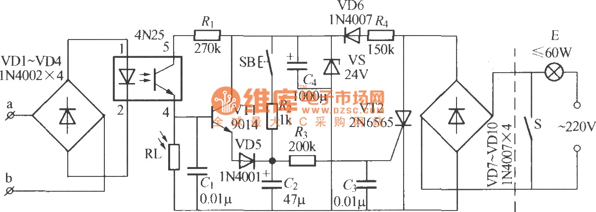
Overall, this circuit design combines automatic and manual control mechanisms to provide efficient lighting solutions, particularly in environments where telephone activity is frequent during nighttime hours. Proper component selection, including relays, resistors, capacitors, and possibly a microcontroller, is essential for the reliable operation of this circuit.The diagram shows telephone control automatic lighting circuit. At night, when telephone rings or master takes up telephone transmitter dialing, the light can lighten; when telephone ringer stopped (no one listen) or on-hook, it can delay 10~40s, then the light can die out itself. Moreover, this circuit also set a light triggering button. The ligh t can lighten about 40s only by pressing the button. 🔗 External reference
Related Circuits
All car batteries require a 12V battery charger, which also applies to marine, RV, and power sports batteries. The high-efficiency lead-acid batteries available today necessitate more effective charging techniques. The battery charger is a crucial tool for prolonging battery...
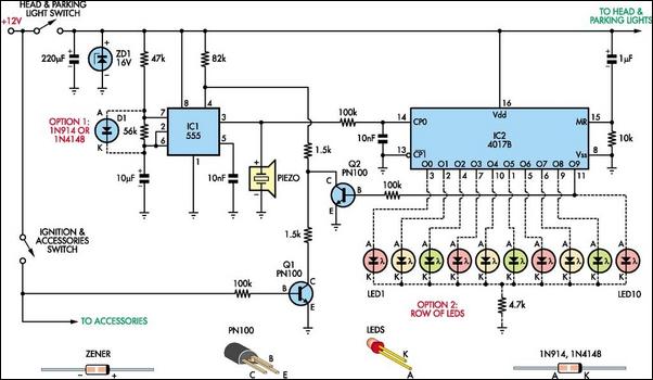
Do you drive an older car without an automatic "lights-on" warning circuit? If so, you have likely accidentally left the lights on and drained the battery on one or more occasions. This headlights reminder circuit will prevent that issue....
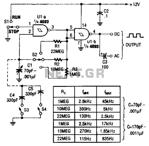
Two gates of a Quad 4093 are utilized in an astable multivibrator configuration. CI is a three-gang 365 pF variable capacitor with its sections connected in parallel. Additionally, S3 and S4 serve to switch in optional extra capacitors. The described...
This ISP Programmer can be utilized for in-system programming or as a standalone SPI programmer for Atmel ISP programmable devices. The programming interface is compatible with STK200 ISP programmer hardware, allowing users of STK200 to also use the software...
The pulser is designed to switch the mains voltage on and off at intervals ranging from just under one second to up to 10 minutes. This functionality is particularly useful for testing mains-operated equipment over extended periods or for...
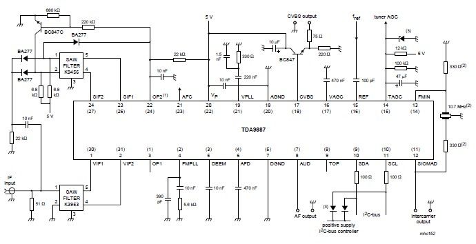
The integrated circuit (IC) is a multistandard vision and sound intermediate frequency (IF) phase-locked loop (PLL) demodulator that operates without the need for alignment. It supports multiple standards, including PAL, SECAM, and NTSC, and is capable of processing both...