
fet audio mixer schematics

The circuit operates by utilizing resistive mixing techniques, which allow for the summation of multiple audio signals without significant distortion or loss of quality. Each input channel is connected to a resistor network that ensures proper impedance matching, thereby preventing loading effects that could degrade the audio signals.
Typically, the circuit will consist of a series of resistors connected to the inputs, with their outputs converging into a single output node. The values of the resistors can be selected based on the desired mixing ratio and to maintain a consistent output level. For example, equal-value resistors can be used for a balanced mix, while varying resistor values can create a weighted mix favoring certain channels.
Power consumption in this circuit is kept low due to the passive nature of the resistive components, making it suitable for battery-operated devices or low-power applications. The overall design can be easily modified to accommodate additional inputs, enhancing its versatility in various audio mixing scenarios.
For implementation, it is essential to ensure that the circuit is housed in a suitable enclosure to minimize interference and maintain signal integrity. Additionally, proper grounding techniques should be employed to reduce noise and improve performance. This circuit is ideal for applications such as audio processing in home theater systems, musical instruments, or any device requiring audio channel mixing.This simple circuit mixes two or more channels into one channel (eg. stereo into mono). The circuit can mix as many or as few channels as you like and consumes very little power. The mixer is shown with two inputs, but you can add as many as you want by just duplicating the "sections" which are clearly visible on the schematic. 🔗 External reference
Related Circuits
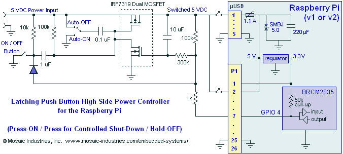
A momentary contact push button switch can be utilized to conveniently turn the Raspberry Pi (RPi) ON and OFF. Pressing the button will apply power to the micro USB header, maintaining power while the Raspberry Pi initializes and starts...
This audio amplifier design utilizes two LM3886 chips per channel in a parallel configuration, based on the PA100 parallel amplifier detailed in National Semiconductor's application note AN1192. The amplifier can deliver approximately 50W into an 8-ohm speaker and 100W...
This compact device serves as a replacement for the input transistors and related circuitry on a single TO-220 style package. A decision was made to substitute the original driver board with a newly fabricated printed circuit board (PCB) designed...
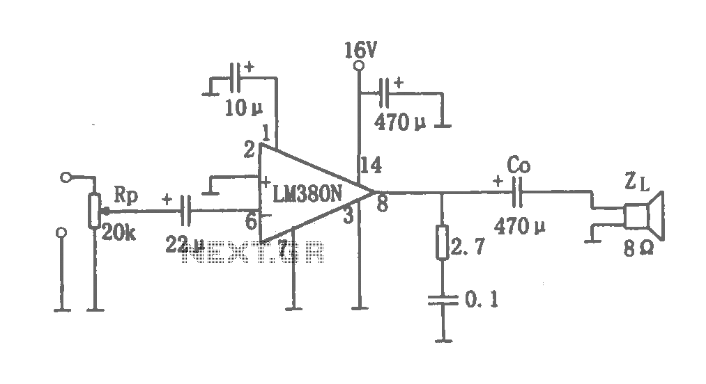
This document details a 2W audio power amplifier circuit that utilizes a 14-pin LM380 package as the amplification element. The input signal is managed by a volume control potentiometer (Rp) rated at 20k ohms, with a coupling capacitance of...
Here a simple design for an attractive tone. They operate on a passive principle, ie without amplification. The circuit only weakened and therefore require no power. As can be seen, the circuit is built with two T-filters in the...
The first choice is usually an integrated circuit designed for the purpose. A typical assortment can be seen on this National Semiconductor page. Discrete designs can also be built with readily available transistors or op-amps, and many designs are...