
Audio conductivity tester with LM3909
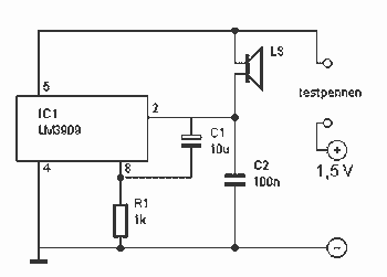
The circuit described utilizes the LM 3909 integrated circuit, which is commonly used in various electronic applications, including resistance testing. This specific application involves a simple resistance measurement setup, where the circuit produces an audible beep through a speaker (LS) when the resistance between two probes falls within a specified range (0 to 100 ohms).
The primary components of the circuit include:
- **R1 (1 kOhm)**: This resistor is likely used to limit the current flowing through the circuit, ensuring that the LM 3909 operates within its safe limits while measuring resistance.
- **C1 (10 µF)**: This capacitor may be employed for filtering purposes, smoothing out any voltage fluctuations that could affect the accuracy of the resistance measurement or the sound output from the speaker.
- **C2 (100 nF)**: This capacitor is typically used for decoupling, helping to stabilize the power supply to the LM 3909 and prevent noise from affecting the circuit's performance.
- **LS (Speaker, 12 to 16 ohms)**: The speaker produces an audible beep when the circuit detects a resistance within the specified range. The volume of the beep can vary depending on the resistance detected, providing a clear indication of the measured value.
- **IC1 (LM 3909)**: The LM 3909 is the heart of the circuit, functioning as a timing and control device. It can generate a tone output based on the input resistance detected by the probes. The frequency and duration of the beep can be modulated based on the resistance value, allowing for a more intuitive understanding of the measured resistance.
The circuit operates by applying a small voltage across the probes. When a resistance within the specified range is detected, the LM 3909 activates the speaker, producing a beep. The frequency of the beep may be influenced by the resistance value, offering a method of determining the resistance level audibly. The design is straightforward, making it suitable for educational purposes or simple testing applications.This works with a small geleidingstestertje LM 3909. It allows a tester beeps when the resistance between the probes between 0 and 100 ? lies. Due to the volume of the beep, the resistance between the probes can be determined. R1 = 1 kOhm C1 = 10 uF C2 = 100 nF LS Speaker = 12 to 16 ? IC1 = LM 3909 🔗 External reference
Related Circuits
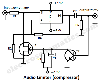
This audio limiter circuit is simple to construct and is compatible with BA741 operational amplifiers, whether in 8-pin or 4-pin configurations. It requires a symmetrical power supply. The circuit is designed to manage audio input levels effectively. The audio limiter...
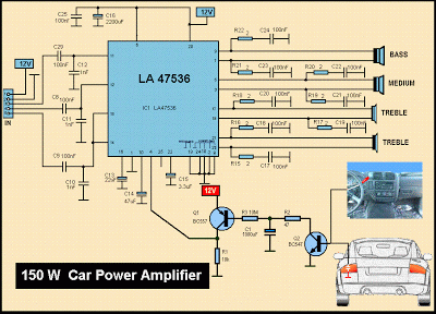
This is a diagram of a car audio active loudspeaker utilizing the LF353 operational amplifier from National Semiconductor. For optimal performance, the NE5532 is recommended to split the audio signal into three frequency bands using an active filter. The...
The project is a variation of the popular POV toy, commonly seen as a beginner electronics project. This year, the decision was made to create a synthesizer kit, incorporating an SPI DAC, audio amplifier, microcontroller, and buttons. Additionally, there...
4 Stage FM Transmitter. This FM transmitter circuit utilizes four radio frequency stages, functioning as a VHF oscillator. It is available for wholesale through fmuser, including the CZE and CZH models of FM transmitters, which are suitable for OEM...
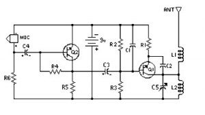
This circuit can be utilized in intercom systems, walkie-talkies, low-power transmitters, and packet radio receivers. Transistors T1 and T2 constitute the microphone preamplifier. Resistor R1 provides the necessary bias for the condenser microphone, while preset VR1 serves as a...
This weblog discusses electronic circuit schematics, PCB design, DIY kits, and electronic project diagrams. The subject circuit is a quality preamplifier with a built-in USB DAC designed for the Leachamp power amplifier. The schematic is based on the PCM2902...