
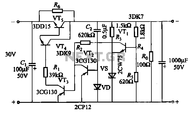
Audio limiter circuit schematic

The audio limiter circuit functions to prevent audio signals from exceeding a predetermined threshold, thereby protecting downstream audio equipment from distortion or damage caused by excessive signal levels. The use of the BA741 operational amplifier allows for reliable signal processing due to its low noise and high gain characteristics.
The circuit typically includes a feedback loop that regulates the output level based on the input signal. When the audio input level rises above the set threshold, the circuit automatically reduces the gain, ensuring that the output remains within a safe range.
In constructing this circuit, attention must be paid to the power supply configuration. A symmetrical power supply is essential for the proper operation of the BA741, which typically requires both positive and negative voltage rails to function effectively.
The layout of the circuit should minimize the length of signal paths to reduce noise and maintain signal integrity. Capacitors may be used at the input and output stages to filter out any unwanted high-frequency noise, improving the overall performance of the limiter.
Additionally, it is important to select appropriate resistor values to set the desired threshold level and gain. The use of variable resistors can provide flexibility in adjusting these parameters according to specific application needs.
Overall, this audio limiter circuit is a valuable tool for audio engineers and hobbyists alike, providing a straightforward solution for managing audio levels in various applications.This audio limiter circuit is easy to build, works with BA741 8pins or 4pins so pay attention and uses a symmetrical power supply. When the audio input lev. 🔗 External reference
Related Circuits

The LTC3113 fixed frequency buck-boost DC-DC converter can be utilized to design various power supply circuits that operate with input voltages that are above, below, or equal to the output voltage. The topology integrated into the IC ensures low...
The soft start circuit refers to a power circuit where the output voltage gradually increases to a specified value, thereby protecting the load circuit from unwanted voltage surges. It can output a voltage of 24V and a current of...
This is a solar tracking circuit designed to harness power from sunlight. The circuit operates optimally by maximizing sunlight exposure to generate electricity. The solar tracking circuit utilizes a combination of photovoltaic (PV) cells, sensors, and a microcontroller to adjust...

The circuit activates a light corresponding to the first button pressed in a "Who's First" game. Three stages are illustrated, but the circuit can be expanded to accommodate any number of buttons and lamps. The described circuit operates as a...
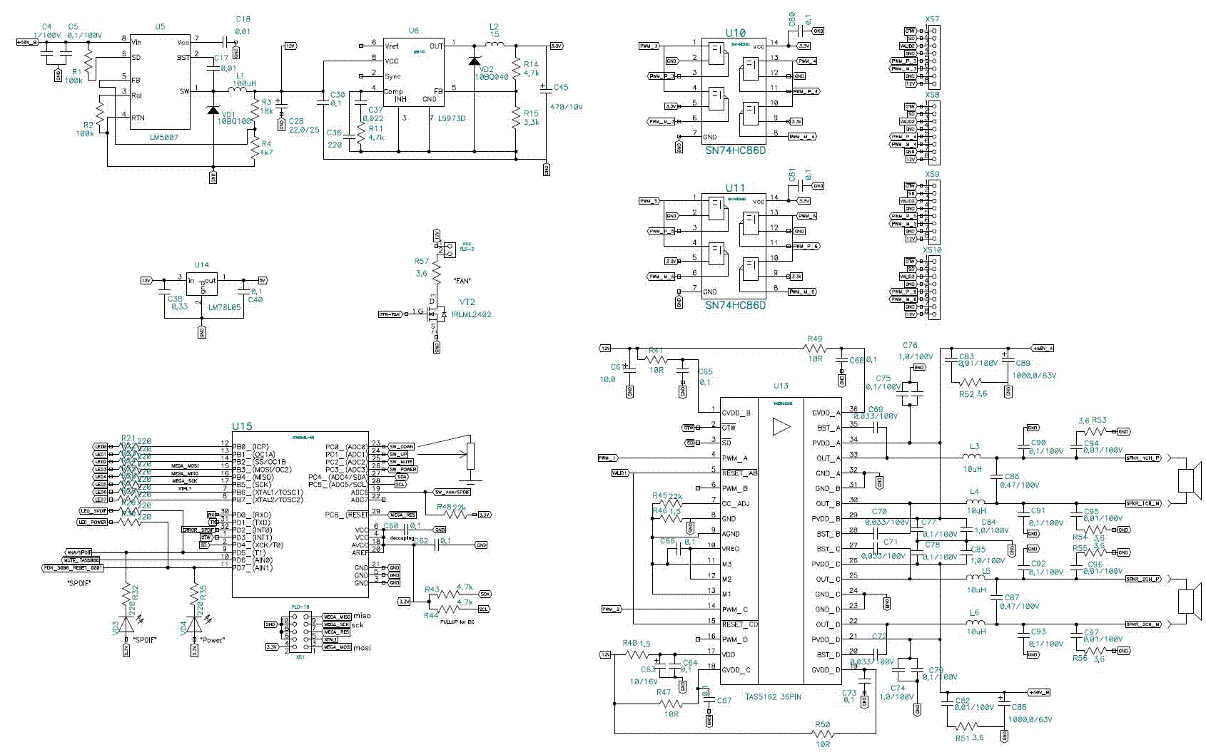
A year ago, a Class-D amplifier was designed based on the TAS5162, PCM1808, and TAS5086. Over the past year, several hundred samples were produced for sale to radio amateurs. Most devices function correctly without issues reported by consumers. However,...
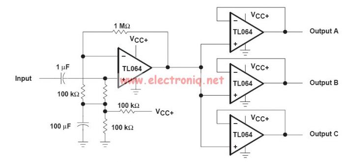
This audio distribution electronic project circuit diagram is designed using the TL064 or TL06 operational amplifiers and some other common electronic parts. The audio distribution circuit utilizes TL064 or TL06 operational amplifiers, which are quad op-amps known for their low...