
USB Audio Interface based DAC PCM2902
The circuit design for the quality preamplifier with built-in USB DAC encompasses several essential elements that contribute to its performance and functionality. The PCM2902 serves as the core of the circuit, providing both digital-to-analog (DAC) and analog-to-digital (ADC) conversion capabilities. This integration allows for seamless digital audio playback and recording, making it suitable for various audio applications.
The circuit is equipped with an SPDIF interface, facilitating high-quality digital audio transmission. The inclusion of buttons for MUTE and volume control enhances user interaction, allowing for straightforward adjustments to audio levels. The implementation of an external low-drop voltage regulator, specifically the LP2951CM, ensures stable power supply to the DAC, which is critical for maintaining audio fidelity. The fixed output voltage of 3.7 V is achieved through a carefully calculated resistor divider network, which stabilizes the DAC's operation.
Attention to detail in the PCB layout is evident, particularly in the separation of digital and analog grounds. This design choice minimizes the risk of noise interference, which can adversely affect audio quality. The single-point ground connection at the USB connector further enhances the circuit's performance by reducing ground loop issues.
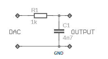
Incorporating a low-pass filter at the output of the DAC is a crucial step in ensuring high-quality audio playback. The recommended first-order RC filter, with a resistor value of 1 kΩ and a capacitor value of 4.7 nF, effectively attenuates high-frequency noise generated during the oversampling process. The choice of a scroll-type ceramic capacitor for this application is advised due to its favorable characteristics in audio circuits.
While subjective listening tests may not reveal significant differences between filtered and unfiltered outputs, the use of the LPF is deemed beneficial in maintaining overall audio integrity within the system. Adjusting the capacitor value to 3.3 nF allows for fine-tuning of the filter's cutoff frequency, providing flexibility in adapting the circuit to various audio requirements. Overall, this preamplifier circuit with USB DAC integration presents a comprehensive solution for high-quality audio processing in modern electronic projects.Welcome to the weblog where we discuss about electronic circuits schematics, PCB design, diy kits and electronic projects diagrams. This is the circuit quality preamplifier with built-in USB DAC for my Leachamp power amplifier. Scheme is PCM2902 datasheet. Circuit includes DAC and ADC, SPDIF input and output of HID and with 3 buttons + MUTE, VOL- and VOL. For playback of high quality needed for external low-drop voltage stabilizer for the DAC. LP2951CM DAC is used, which was readily available in local stores. Output voltage is fixed at about 3. 7 V with two resistors. Circuit board is designed with regard to the placement of good land, and the separation of digital and analog ground. These earth are connected in a single point in a USB connector. The PCM2902 data sheet is recommended to connect a low pass filter the DAC output to filter high frequencies above audioband produced by the conversion of oversampling.
Digital integrated circuits that includes LPF filter frequency above 100 kHz. In the Notes application filter on the pages of the manufacturer recommends first-order LPF (simple RC) or 2 nd order with amplifiers operating as a preamp that works well. I simple RC LPF with the recommended values R and C 1k 4N7. It is best to use the scroll-type ceramic capacitor in place. I did not hear the difference in sound between the connection filter or not, but with respect to other components in an audio chain is best used.
For maximum cutoff frequency that can change the capacitor value of 3n3 🔗 External reference
Related Circuits
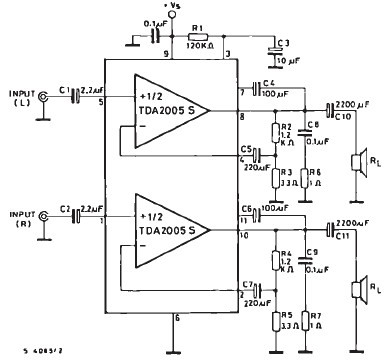
The TDA2005 car audio amplifier circuit is specifically designed for use in devices such as car radios, CD players, and similar equipment. This amplifier is based on the TDA2005 audio integrated circuit (IC), capable of delivering a maximum output...
This unit is designed to monitor the audio output level across a loudspeaker during the alignment of radios. A simple passive circuit arrangement has been utilized, as high precision is not required. The circuit functions as a voltage-doubling rectifier...
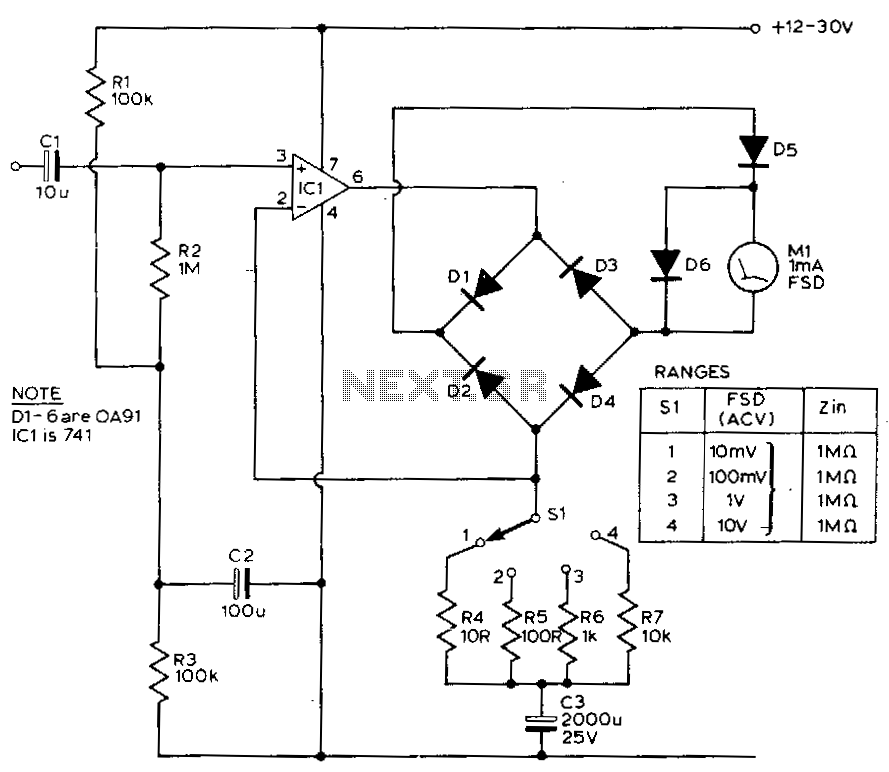
This circuit exhibits a flat frequency response from 8 Hz to 50 kHz, maintaining a -3 dB level at the 10 mV range. Furthermore, while the upper frequency limit remains consistent across less sensitive ranges, the lower frequency limit...
Assembly is straightforward; simply follow the PCB overlay. Ensure that the integrated circuit and the electrolytic capacitors are oriented correctly. The electrolytic capacitors are polarized, marked with a + or - sign, and must be installed properly into the...
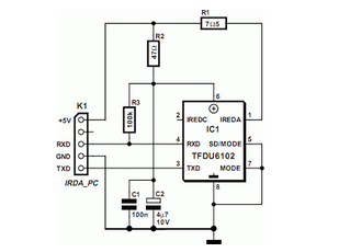
Many modern motherboards are equipped with an infrared data interface compliant with the IrDA standard, but this interface is not very often used. The infrared data interface, adhering to the Infrared Data Association (IrDA) standard, provides a wireless communication...
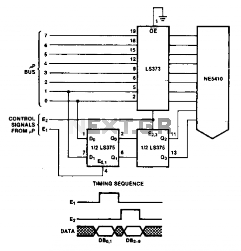
The double latch technique ensures that valid data is latched to the Digital-to-Analog Converter (DAC) until it is updated by the E2 pulse. The timing of this process will depend on the specific processor utilized. The double latch technique is...