
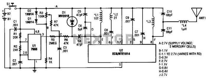
Simple video amplifier circuit diagram
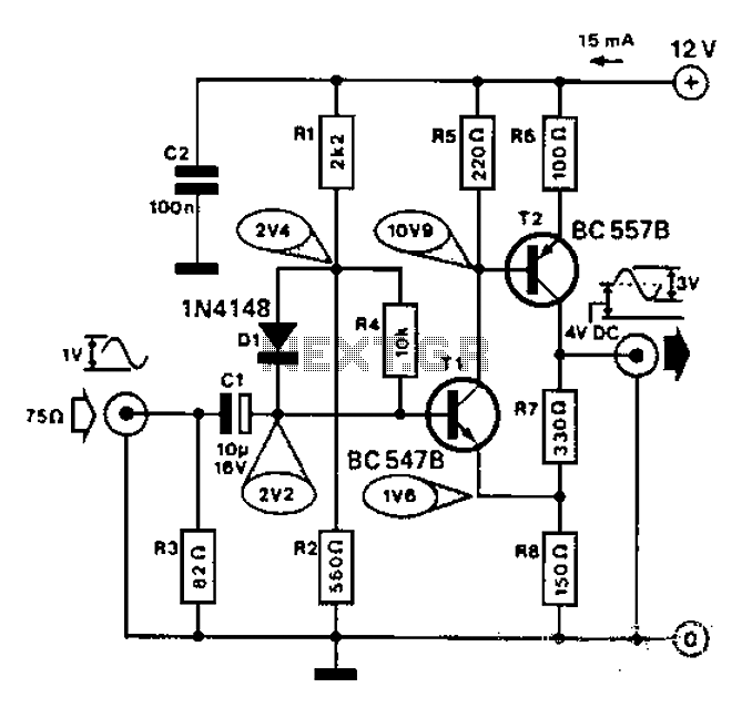
The described circuit is an amplifier designed for applications involving cameras or computers that interface with black and white television systems. The amplifier features a gain of 3, which indicates that the output signal will be three times the amplitude of the input signal. This is particularly useful in enhancing the signal strength for better image quality in low-light conditions or when the source signal is weak.
The bandwidth of 10 MHz signifies the range of frequencies over which the amplifier can operate effectively. A bandwidth of this magnitude allows the amplifier to handle a variety of signals without significant distortion, making it suitable for video applications where maintaining signal integrity is crucial.
In practical terms, the amplifier circuit may include several key components such as resistors, capacitors, and operational amplifiers (op-amps). The gain can be set using a feedback resistor configuration, while capacitors may be employed to filter out unwanted noise and ensure stable operation across the specified bandwidth.
The design considerations for such an amplifier would also include power supply requirements, input and output impedance matching to ensure compatibility with the connected devices, and thermal management to prevent overheating during operation.
Overall, this amplifier serves as an essential component in systems requiring reliable video signal amplification, ensuring quality performance in the specified applications. Commonly used for camera or computer with B/W TV connection, the bandwidth of the amplifier gain of 3 and having 10MHz.
Related Circuits
A JFET-bipolar cascode circuit is designed to deliver complete video output for driving the cathode of a CRT. The configuration offers an approximate gain of 90. The cascode arrangement mitigates issues related to the Miller capacitance of the JFET...
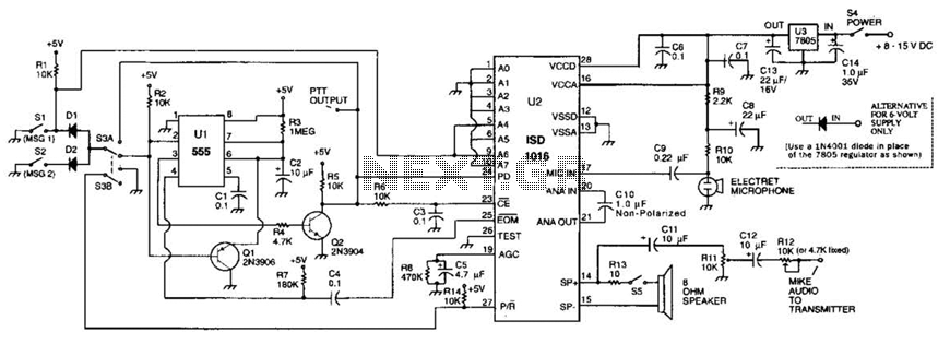
The circuit utilizes an ISD1016 audio record/playback chip from Information Storage Devices, Inc. to record and playback messages on demand. While it is primarily designed for use with transmitters, it can also serve as an electronic notepad or similar...
This transmitter emits an FM signal within the 88 to 108 MHz frequency range, featuring a tone of 19 kHz. This tone can activate the FM MPX pilot carrier indicator, allowing interfacing with external devices. L4 is designed for...
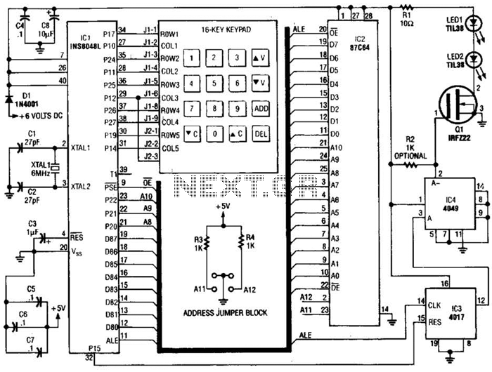
This transmitter can be utilized for multiple applications. An INS8048L microprocessor produces various codes based on keypad inputs. These codes are modulated onto a 40-kHz carrier frequency. Additionally, Q1 drives infrared LEDs LED1 and LED2. The transmitter circuit primarily consists...
The circuit is a microphone amplifier for use with low impedance (~200 ohm) microphones. It will work with stabilized voltages between 6-30VDC. If you don`t build the impedance adapter part with T1, you get a micamp for higher impedance...
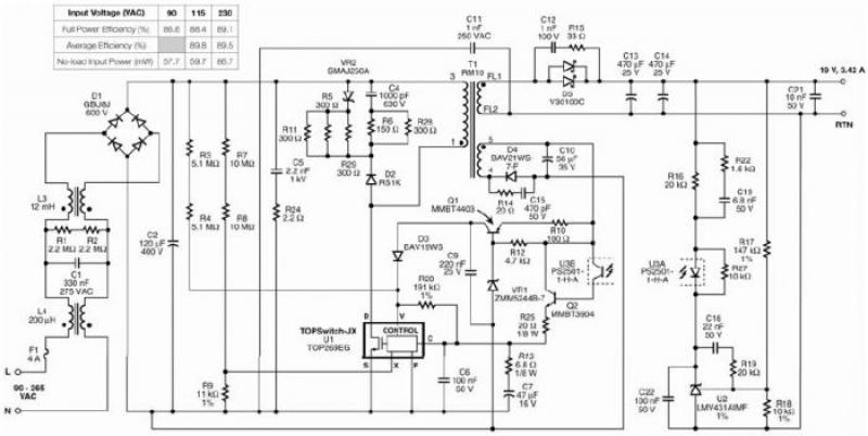
The TOP269EG off-line switcher integrated circuit (IC), designated as U1, can be utilized in a flyback configuration to create a simple and highly efficient power adapter for notebook laptops. The TOP269EG features an integrated 725 V MOSFET and a...
Warning: include(partials/cookie-banner.php): Failed to open stream: Permission denied in /var/www/html/nextgr/view-circuit.php on line 713
Warning: include(): Failed opening 'partials/cookie-banner.php' for inclusion (include_path='.:/usr/share/php') in /var/www/html/nextgr/view-circuit.php on line 713