
IC Controlled Emergency Light With Charger Circuit
The circuit operates on a dual-function basis, providing both emergency lighting and battery management. The NE555 timer is configured in astable mode, generating a continuous square wave signal that controls the switching of the MOSFETs, which in turn drive the transformer to produce the necessary AC voltage. The design ensures that during a power outage, the system seamlessly transitions from mains power to battery power, allowing for uninterrupted operation of the connected load.
The overcharge protection mechanism is critical for maintaining battery health, preventing damage from excessive charging. The use of the LM308 comparator allows for precise monitoring of the battery voltage, ensuring that the charging process is halted at the appropriate threshold. This feature not only extends battery life but also enhances safety by reducing the risk of overheating or leakage.
In terms of component selection, the NE555 timer is widely recognized for its reliability and ease of use in timing applications. The MOSFETs chosen for this circuit should have adequate current ratings to handle the load, and their thermal management is crucial for long-term operation. Proper heat sinking will prevent thermal runaway, ensuring that the MOSFETs operate within safe temperature limits.
Overall, this circuit is a practical solution for emergency lighting needs, combining efficient power conversion with essential battery management features. The thoughtful integration of components and protections makes it suitable for various applications where reliable backup lighting is necessary.Here is the circuit diagram of IC Controlled Emergancy Light With Charger or simply 12V to 220V AC inverter circuit. The circuit shown here is that of the IC controlled emergency light. Its main features are: automatic switching-on of the light on mains failure and battery charger with over-charge protection.
When mains is absent, relay RL2 is in de-energized state, feeding battery supply to inverter section via its N/C contacts and switch S1. The inverter section comprises IC2 (NE555) which is used in stable mode to produce sharp pulses at the rate of 50 Hz for driving the MOSFETs. The output of IC2 is fed to gate of MOSFET (Q4) directly while it is applied to MOSFET (Q3) gate after inversion by transistor Q2.
Thus the power amplifier built around MOSFETs Q3 and Q4 functions in push-pull mode. The output across secondary of transformer T2 can easily drive a 230-volt, 20-watt fluorescent tube. In case light is not required to be on during mains failure, simply flip switch S1 to off position. Battery overcharge preventer circuit is built around IC1 (LM308). Its non-inverting pin is held at a reference voltage of approximately 6. 9 volts which is obtained using diode D5 (1N4148) and 6. 2-volt zener D6. The inverting pin of IC1 is connected to the positive terminal of battery. Thus when mains supply is present, IC1 comparator output is high, unless battery voltage exceeds 6. 9 volts. So transistor Q1 is normally forward biased, which energises relay RL1. In this state the battery remains on charge via N/O contacts of relay RL1 and current limiting resistor R2. When battery voltage exceeds 6. 9 volts (overcharged condition), IC1 output goes low and relay RL1 gets de-energised, and thus stops further charging of battery.
MOSFETs Q and Q4 may be mounted on suitable heat sinks. 🔗 External reference
Related Circuits
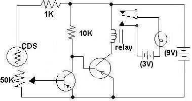
This circuit was submitted by Adam from Canada who is still at school. I have provided the text. The two transistors are used as a direct coupled switch, Adam used 2SC711 but any general purpose transistor will do e.g....
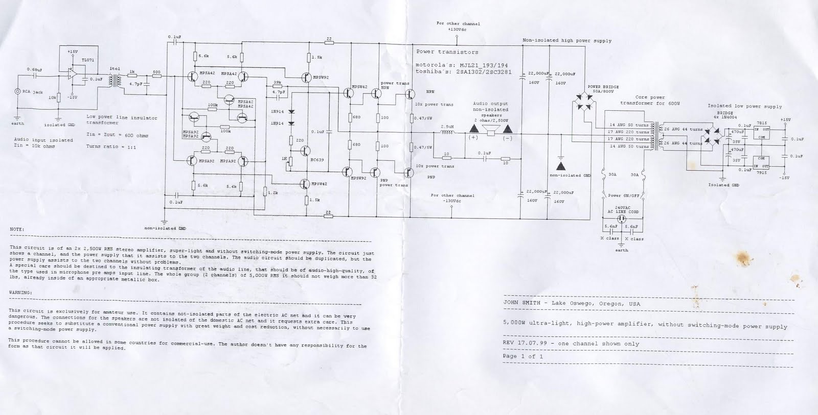
This device is a 2x2, 500W RMS stereo amplifier, designed to be super-lightweight and equipped with a switching-mode power supply. The device features a single channel display and specifies the power output it provides to both channels. The audio...
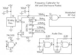
The following circuit illustrates an AM/Shortwave Radio Frequency Calibrator Circuit Diagram. This circuit is based on the 74LS93 IC. Features: The .. The AM/Shortwave Radio Frequency Calibrator Circuit utilizes the 74LS93 integrated circuit, which is a 4-bit binary counter. This...

Integrated circuit gates IC1-a and IC1-b form a monostable multivibrator, whose time constant is determined by capacitor C2 and resistor R3. When the transmitter is dekeyed and then almost immediately rekeyed, point TX+ goes low, causing pin 1 to...
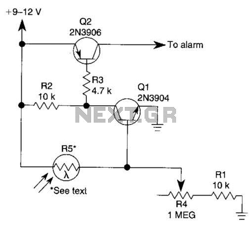
The circuit functions as a sensor capable of triggering an alarm without direct contact from an intruder. It utilizes a visible or invisible light source that illuminates the sensor, maintaining the detection loop in a normally closed state. As...
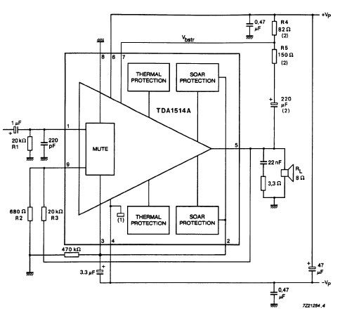
The TDA1514 audio amplifier circuit design is an electronic project capable of delivering high audio power output using a specialized audio integrated circuit (IC) and a few common components. Manufactured by Philips Semiconductor, the TDA1514 audio IC can provide...
Warning: include(partials/cookie-banner.php): Failed to open stream: Permission denied in /var/www/html/nextgr/view-circuit.php on line 713
Warning: include(): Failed opening 'partials/cookie-banner.php' for inclusion (include_path='.:/usr/share/php') in /var/www/html/nextgr/view-circuit.php on line 713