
DC motor servo control circuit diagram
The described circuit operates as a position control system for a motor, utilizing a feedback mechanism to achieve precise positioning. The input DC voltages, denoted as E and O, are applied to the motor driver circuit, which translates these voltages into corresponding motor movements. The motor is designed to respond to the input voltages by adjusting its position along a defined range.
The position feedback is provided by a potentiometer, which is mechanically linked to the motor's shaft. This potentiometer has a resistance of 1k ohms and functions as a voltage divider. As the motor rotates, the wiper of the potentiometer moves along the resistive track, generating a voltage that is proportional to the motor's position. This feedback voltage is then compared to the input voltage using a differential amplifier.
The differential amplifier plays a crucial role in determining the operational state of the motor. When the voltage from the potentiometer wiper matches the input voltage (E or O), the output of the differential amplifier becomes zero. This condition indicates that the motor has reached the desired position and should remain stationary. Conversely, if the input voltage differs from the feedback voltage, the differential amplifier produces a non-zero output, prompting the motor to either move forward or reverse, depending on the polarity and magnitude of the signal.
This feedback control system ensures that the motor can accurately position itself in response to varying input voltages, allowing for precise control in applications such as robotics, automation, or any system requiring accurate positioning. Proper tuning of the circuit components, such as the potentiometer value and the gain of the differential amplifier, is essential for optimal performance and stability of the motor control system.In the circuit, when E, O are input DC voltage, the motor will be moved to a position corresponding with the voltage. The potentiometer connected to the same coaxially of motor is used as position feedback. When the given voltage is equal to 1k potentiometer wiper contact voltage, the differential amplifier output is zero, so the motor is stationary; Otherwise, the motor will be transferred or reversal according to the size of the signal.
🔗 External reference
Related Circuits
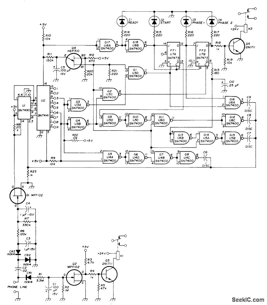
A repeater or other unattended equipment can be activated or deactivated using a standard telephone. The process involves calling the remote station, allowing it to ring three times, hanging up, waiting for 20 seconds, redialing the number, and letting...
The circuit in Figure 1 converts pulse information to a clean dc voltage by the end of a single incoming pulse. In another technique, an RC filter can convert a PWM signal to an averaged dc voltage, but this...
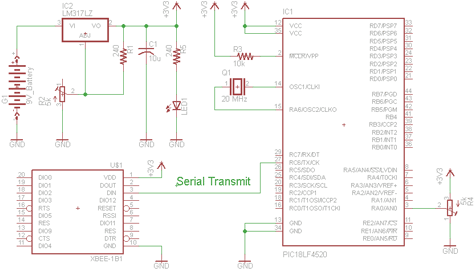
There are two schematics to examine for constructing a transmitter/receiver system. The first schematic is the transmitter, featuring a variable trimpot connected to RA0. The trimpot's value will be transmitted from the Tx pin of the PIC to the...
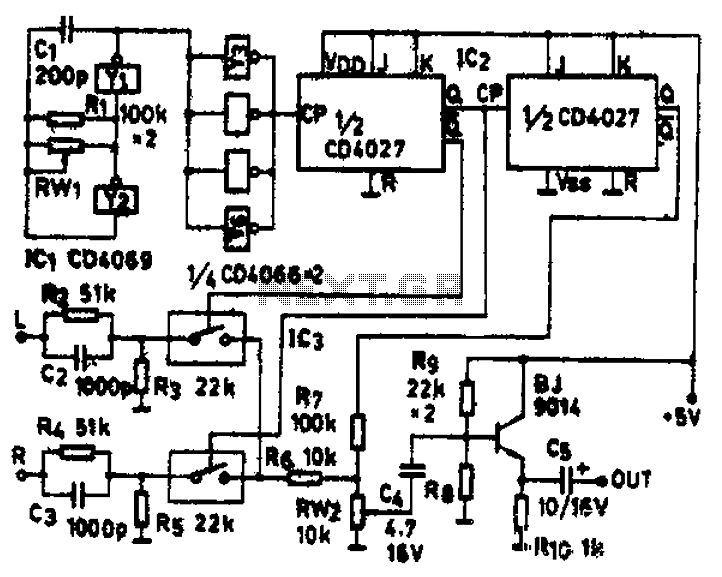
The circuit schematic diagram features IC1 (4069) and components Y1 and Y2, which together form a frequency oscillator operating at 76 kHz. Components Y3 to Y6 provide isolation and shape the output into the IC2 (CD4027) dual JK flip-flop,...
Upon entering the password, the application, in this case "LED," will illuminate. In this digital locking system project, the interfacing of a keypad and a 16x2 LCD with a microcontroller will be explored, along with the accompanying code. This...
The wiring diagram for the clock and radio screen illumination for a 1999 Mercury Sable with a 3.0L VIN U. The vehicle is a Mercury Sable GS, not LS. Assistance is required to identify which circuit in the diagrams...