
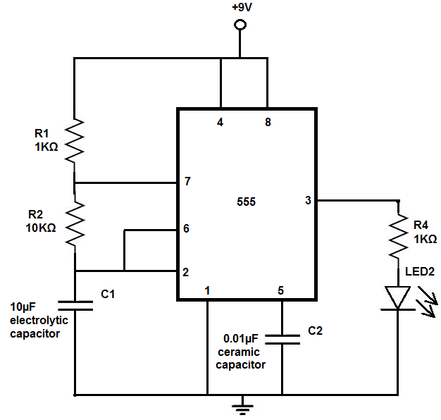
LED Flasher Circuit
For constructing this circuit, several jumper wires are required to connect the resistors and capacitors to the 555 timer chip, as the connections can become complex. Jumper wires facilitate the organization of the circuit on a breadboard, preventing clutter. The output of a 555 timer consists of square waves, characterized by three critical time measurements: the total duration of the square wave (the time it is high and low), the time it is high (T), and the duty cycle, which represents the proportion of time the square wave is high relative to the total period. For instance, if the total duration of a square wave is 1 second and it is high for 0.2 seconds, the duty cycle is 20%, indicating the LED is on for 20% of the cycle. This duty cycle is crucial for applications like the LED flasher circuit, as it dictates how long the LED remains lit compared to how long it is off.
For example, a duty cycle of 20% means the LED flashes on for 20% of the cycle and remains off for 80%. Conversely, an 80% duty cycle results in the LED being on for 80% of the cycle and off for 20%. The choice of resistor and capacitor values significantly affects the cycle duration; larger values lead to longer cycles. For instance, using 1 MΩ resistors and a 100 µF capacitor could yield a total cycle time of 210 seconds, with the LED on for 140 seconds and off for 70 seconds, which is excessively long for a flashing effect.
To achieve a visible flashing effect, lower values for the resistors and capacitors must be chosen. However, if the values are too small, the LED may appear to be constantly lit, as in the case of using 1 kΩ resistors and a 0.1 µF capacitor, resulting in cycles that are too brief for human perception. Therefore, it is essential to select appropriate resistor and capacitor values to achieve a desirable flashing effect. With the correct values, each cycle can last just a few milliseconds. An example of a practical application of this concept can be found in the Arduino LED Flasher Circuit, which can be easily constructed using a microcontroller like Arduino.
In summary, the 555 timer in astable mode serves as a reliable means for generating variable frequency square wave outputs, which can be effectively utilized for LED flashing circuits. The design flexibility allows for adjustments in the duty cycle and frequency by varying the resistor and capacitor values, providing a robust platform for various electronic applications.The 555 timer chip is a very versatile IC, because when connected correctly, it can it can create pulses of current at specific time intervals decided by the resistor-capacitor (RC) network. When a 555 timer creates pulses in this way, the LED doesn`t stay constantly on. It only turns on at a pulse and then shuts off after the pulse has passed. An d it does this in a never-ending cycle, which creates the flashes of light. To make the 555 timer chip create pulses, it must be placed in astable mode. Astable mode simply means that the 555 timer has no stable state. It switches constantly between high and low, or on and off. This is why this mode is also called oscillator mode, because it uses the 555 timer an oscillator, which creates square wave signals. For this circuit, you will need several jumper wires because to connect all the resistors and capacitors to the 555 timer chip does become complicated.
To simply the breadboarding of this circuit, jumper wires help to space out the circuit so that everything isn`t jumbled on top of each other. Again, the output of a 555 timer are square waves. There are 3 important time measurements for a square wave. There is the total length of the square wave (the time it is on and off or high and low), there is the length of time it is high (T.
The amount of time that the square wave is high is its duty cycle. So, for example, if the total time of a square wave is 1 second and it`s high for 0. 2s, it has a duty cycle of 20%, because it`s on for only 20% of the cycle. The duty cycle is very important for an application like this LED flasher circuit. The duty cycle we choose determines how long the LED will stay on for compared to how long it is off for. Again, as an example, if we set our duty cycle to be 20%, this means the LED will flash on for 20% of the cycle and be off for 80% of the cycle.
If we choose a duty cycle of 80%, the LED will be on for 80% of the cycle and off for 20% of the cycle. Thus, our duty cycle is very important. According to the above formulas, the larger value we use for the resistors and the capacitor, the longer the cycle will be.
If we use very large values such as 100KG or 100G‚ µF, we will have very large cycles. For example, let`s say we make R1 and R2 resistors both 1MG resistors and C1 100G‚ µF. This would produce a total time period of 210 seconds for the cycle. Of this 210s, the LED would be on for 140s and off for 70s. This is not what we want at all. This is way too long. This would not produce a LED flasher. We must choose much lower resistor and capacitor values in order to see a flashing or flickering effect. However, on the other extreme, we do not want to choose values which are too small as well. If we do, the human eye won`t be able to detect that it has even turned on. For example, if we choose 1KG resistors and a 0. 1G‚ µF capacitor, the time cycle and the on-off cycle would be too short. It will be as if the LED is constantly on. Therefore, we must choose a precise range of values to see the flashing effect. With these values, each cycle would last just a few millionths of a second. To see a project of an LED flasher being built with an arduino board, see Arduino LED Flasher Circuit.
This same flasher can easily be built with a microcontroller like arduino. 🔗 External reference
Related Circuits
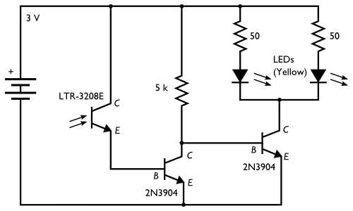
Here is an inexpensive electronic circuit that can be built to place in a Jack-o'-lantern. It provides power to drive a few LEDs at night and automatically turns them off during the daytime. This is a simple and automatic...

This circuit for starting arc jets and controlling them in steady operation is capable of high power efficiency and can be constructed in a lightweight form. The design comprises a pulse-width-modulated power converter, which is configured in a closed...
An RF probe is a circuit designed for testing equipment that converts high-frequency signals into DC voltage. This conversion facilitates the measurement of RF voltages for testing or adjusting transmitters, receivers, and modulators. The RF probe circuit outlined here...
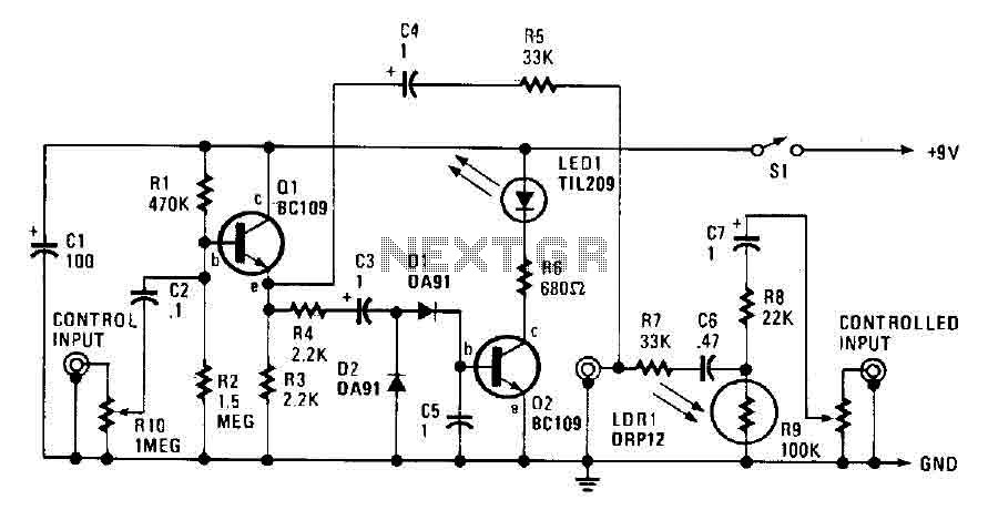
The automatic fader reduces the background music level when narration is in progress. The control input through RIO, a preset audio level control, is directed into an emitter-follower buffer stage (Q1). This buffer provides high input impedance and ensures...
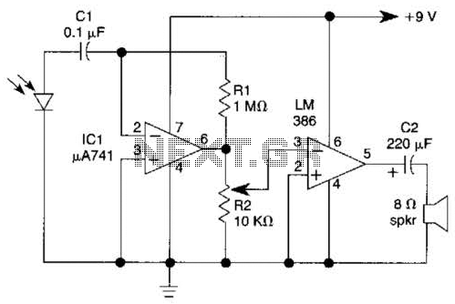
This light-wave receiver comprises a 741 operational amplifier functioning as a preamplifier and an LM386 operational amplifier serving as a power amplifier. The gain control is managed by a potentiometer labeled R2. Various types of detectors can be utilized...
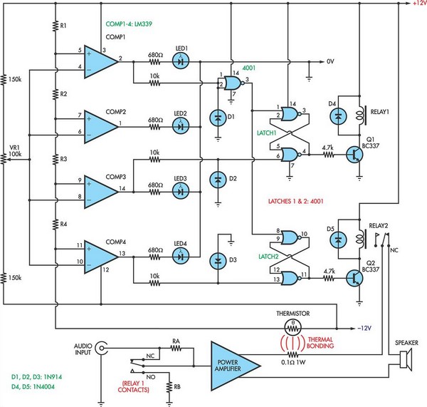
When the voltage on the non-inverting input of each comparator exceeds the voltage at its inverting input, the output transitions to a high state, activating the corresponding LED. NOR gate latches are connected to the outputs of the third...