
Thyristor cascade speed control circuit

The circuit operates on the principle of a wound rotor induction motor, which allows for variable speed operation by manipulating the rotor's electrical characteristics. The induction motor generates an electromotive force (EMF) in the rotor due to the interaction between the rotating magnetic field produced by the stator and the rotor's windings. The induced voltage U reflects the difference in frequency between the stator and rotor, which is essential for determining the motor's operational speed.
The bridge rectifier plays a critical role in converting the three-phase AC voltage to a stable DC voltage (UD), which is necessary for the inverter's operation. This inverter is responsible for converting the DC voltage back to AC voltage, enabling the motor to operate under different frequency conditions. The feedback network from the inverter transformer is crucial for maintaining stability and efficiency in the system, as it allows for real-time adjustments based on the motor's performance.
The inverter voltage (Up) is added to the rotor circuit EMF, enhancing the overall voltage available to the rotor. By controlling the inverter angle (Lu), the system can effectively adjust the magnitude of Up, thereby allowing for precise speed control of the motor. This method of speed regulation is particularly advantageous in applications requiring variable speed operation, as it provides flexibility and efficiency in motor control. The overall design emphasizes the integration of power electronics with traditional motor systems, showcasing advancements in control strategies for induction motors.Circuit shown in Figure 3-170. Wound rotor induction electric motive at different speeds induced in the rotor voltage (turn difference frequency EMF) U. A s U, o (Us0 is sl when the rotor open circuit voltage). The three-phase voltage through a bridge rectifier into a DC voltage UD, UD and then by the inverter to AC inverter power, the inverter transformer feedback network. Then the inverter voltage Up can be viewed as added in the rotor circuit EMF. Inverse control variable inverter angle Lu, you can change the size of Up in order to achieve speed control.
Related Circuits
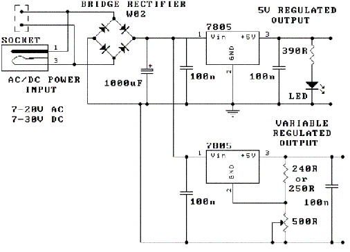
The following circuit illustrates how to build a variable DC power supply circuit. This circuit is based on the 7805 IC. Features: other output is ... The variable DC power supply circuit utilizing the 7805 integrated circuit (IC) is designed...
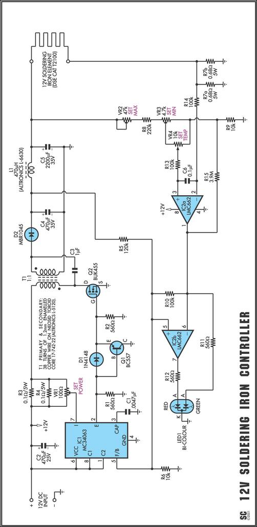
One reason commercial soldering stations are costly is that they typically use soldering irons equipped with built-in temperature sensors, like thermocouples. This circuit design eliminates the necessity for a specialized sensor by directly sensing the temperature of a soldering...

This sensor switch circuit features nine channels and consists of three integrated circuits along with several resistors. The 74HC147, which has a high input impedance, enables the use of 4.7 MΩ resistors to establish a logic level "high" for...
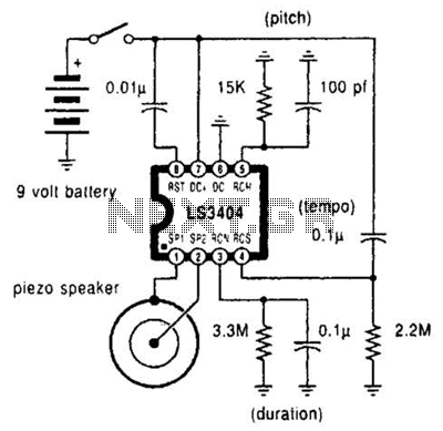
A high-quality melody circuit produces a slow decay waveform that generates chime-like notes. The pitch, tempo, and duration of the notes are all adjustable. The melody circuit is designed to offer a versatile sound generation capability, making it suitable for various...
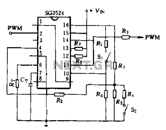
The SG3524 is utilized solely as a pulse width modulator. The error amplifier is configured in a follower arrangement. As illustrated in Figure 10-7, the ACR output connects to PWM output pin 2, which serves as the control signal....
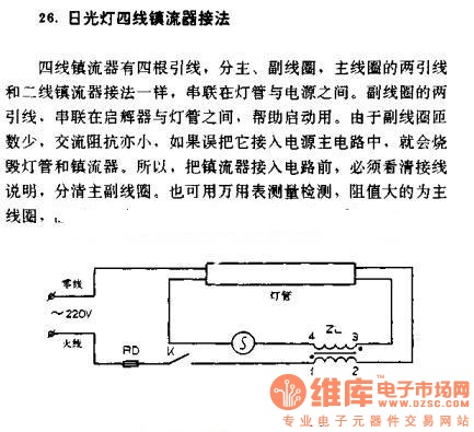
The four-wire ballast connection of a fluorescent lamp consists of four lead wires, which include main and auxiliary coils. The connection of the two lead wires in the main coil is similar to that of a second-line ballast; both...