
Transistor Circuits
The circuits described encompass various configurations and components essential for RF applications. The RF amplifier circuit featuring the TUT transistor demonstrates the significance of grounding and shielding in minimizing interference and enhancing performance. The grounding of the transistor case, along with the use of a metal shield on the printed circuit board, forms a critical part of the design to ensure stability and reliability in RF signal transmission.
In the circuit with the DUT transistor, the use of variable or trimmer capacitors indicates a focus on tuning and optimizing the circuit for specific frequency responses, which is paramount in RF applications. The coaxial connectors facilitate the connection of RF signals while maintaining impedance matching, which is vital for minimizing signal reflections and losses.
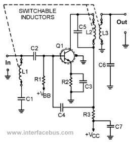
The VHF transistor amplifier circuit builds on these principles by incorporating additional shielding and ganged inductors, which allow for dynamic tuning of the circuit's response characteristics. The design of the FET amplifier with a four-lead package further emphasizes the importance of grounding for thermal management and signal integrity in high-frequency operations.
Overall, the collection of circuits serves to illustrate the complexities and requirements of designing effective RF amplifiers, highlighting the interplay of various components and configurations to achieve desired operational characteristics.This page lists a few transistor circuits not found on other pages because no topic exists. However the circuits do serve to make some specific point, but do not come with a description. An example of an RF amplifier circuit using a transistor is shown below. The transistor is identified as TUT which stands for Transistor Under Test. The point of the schematic is to show the additional components required in an RF circuit. Also note that the case of the transistor is grounded and there appears to be metal shield being used on the printed wiring board. Although there is no clear-cut definition of what the dashed grounded lines means. Many transistor cases have an un-committed metal case or tab that may be used for either grounding or heat dissipation.
Note that C5 is a Feed-through Capacitor used to suppress EMI between inter-panel connections. The next circuit example below is also an RF circuit. In this case the transistor is labeled as DUT for Device Under Test, because the circuit is a setup to test operating characteristics of the transistor. Note the heavy use of variable capacitors, or trimmer capacitors normally implying an RF circuit. Coaxial connectors are shown as 50 ohm inputs and outputs, depicted by the cycle around the dot. The next circuit is also another RF circuit except this time it depicts an actual VHF transistor amplifier.
The difference here is the shielded screen around the transistor case, and the switchable inductors [which are ganged together]. This next circuit is another RF FET amplifier. This particular example uses a four lead package with the fourth lead being connected to the transistor case, which is than grounded.
Again 50 coax connectors are shown. 🔗 External reference
Related Circuits
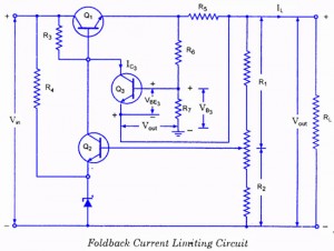
If the load resistance (RL) is reduced or the load terminals are accidentally shorted, a very large load current will flow, potentially damaging the pass transistor (Q1), diode, or other components. Fuse protection may not be sufficient, as the...

This circuit represents a negative resistance configuration. All previous circuits utilize RC time constants to achieve resonance. LC combinations can also be employed, providing good frequency stability, high Q factor, and rapid startup. In this circuit, a signal input...
The project involves adapting a curve tracer schematic, likely based on Metzger's circuit from the early 1970s, to integrate an ADC capture system and output the data to a 320x256 ELD panel. Additionally, a serial output will be included...
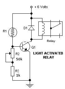
This light-dark switch activated relay circuit schematic represents one of the simplest electronic circuits designed to activate other electronic devices based on light or darkness. It requires a single electronic relay and a few common components that are not...
This circuit operates on 12V DC instead of mains AC. This is an advantageous approach for those who prefer not to deal with circuits connected directly to mains voltage or wish to power the stroboscope using batteries. Flash Slave...

Below 10 MHz, the development of engineering models is relatively straightforward and not significantly influenced by printed circuit board layout. In the VHF range, parasitic circuit elements and unwanted coupling can severely impact efforts to achieve cost-effective performance without...
Warning: include(partials/cookie-banner.php): Failed to open stream: Permission denied in /var/www/html/nextgr/view-circuit.php on line 713
Warning: include(): Failed opening 'partials/cookie-banner.php' for inclusion (include_path='.:/usr/share/php') in /var/www/html/nextgr/view-circuit.php on line 713