
Audio Level Meter
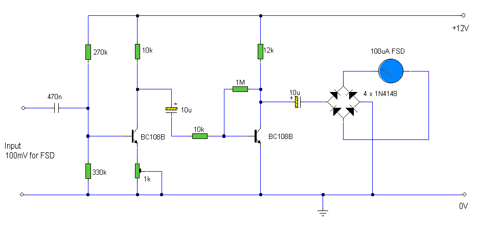
The circuit is designed to accurately measure audio signals across a wide frequency range, making it suitable for various audio applications. The two common emitter amplifiers serve to amplify the input signal, ensuring that even low-level audio signals can be effectively measured. The first amplifier stage's preset resistor allows for fine-tuning of the circuit, ensuring that the meter can be calibrated to achieve full-scale deflection (FSD) at the desired input level.
The biasing of the final amplifier stage at approximately half the supply voltage is a crucial design consideration. This configuration maximizes the AC voltage swing, which is essential for capturing the dynamic range of audio signals without distortion. The inclusion of a 10µF DC blocking capacitor is vital for preventing any DC component from affecting the measurement, allowing only the AC audio signal to pass through to the rectification stage.
The full-wave bridge rectifier is an integral part of the circuit, as it converts the amplified AC signal into a varying DC voltage that can be read by the meter. The instantaneous nature of the meter reading is a key feature, providing real-time feedback on audio levels. However, users should be aware that this design does not capture peak levels, which can be important in certain audio applications. For those requiring peak level measurements, an alternative peak reading audio level meter is suggested.
Overall, this circuit is an effective solution for audio level monitoring, combining simplicity with functionality to meet the needs of audio engineers and technicians.The circuit has a flat frequency response from about 20Hz to well over 50Khz. Input sensitivity is 100mV for a full scale deflection on a 100uA meter. Built on two common emitter amplifiers, the first stage has a preset resistor which may be adjusted for a FSD. The last stage is biased to operate at roughly half the supply voltage for maximum ac v oltage swing. Audio frequencies are passed through the 10u dc blocking capacitor and the full wave bridge rectifier converts the signal to a varying dc voltage. Note that the meter reading is instantaneous and will not provide a "peak" reading. A peak reading audio level meter is also available on this page 🔗 External reference
Related Circuits
Redesign a complex solution using minimal external components, resulting in a low-cost application that provides high-precision measurements. This digital thermometer microcontroller project utilizes a watchdog timer function to measure temperature. The watchdog timer (WDT) on all PIC microcontrollers has...
A digital voltmeter, or any voltmeter with millivolt resolution and high input impedance, can be utilized as a temperature-to-voltage adapter. The described temperature-to-voltage adapter is designed to convert temperature readings into corresponding voltage outputs, suitable for interfacing with digital voltmeters....
Car audio amplifier schematic diagram. Given the voltage of the car is +12 V, there is an opportunity to take power over a threshold. The solution involves using two amplifiers in a bridge connection, theoretically quadrupling the output power...
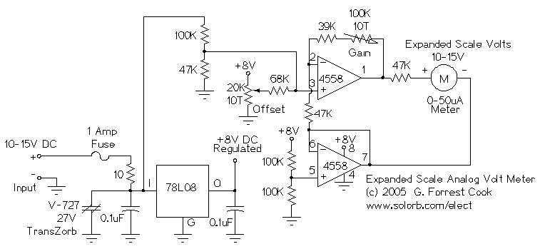
This circuit is used to measure the voltage on a 12V (nominal) lead acid rechargeable battery system. It was specifically designed for use in solar powered systems, but is general enough that it can be used for automotive or...
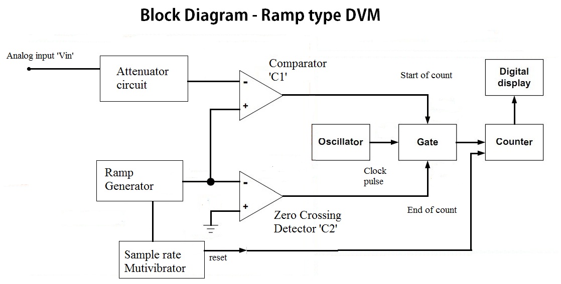
In the voltage-to-time conversion section, the analog input voltage is directed to the attenuation circuit. The attenuated signal is compared with the ramp signal generated by the ramp generator, as indicated in the block diagram, through the input comparator...
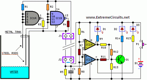
The entire project was developed at the request of a friend. Its purpose is to remotely monitor the water level in a metal tank located in the attic using a simple control unit placed in the kitchen, several floors...