
Fahrenheit Thermometer Using LM35 Temperature Sensor IC
The described temperature-to-voltage adapter is designed to convert temperature readings into corresponding voltage outputs, suitable for interfacing with digital voltmeters. This adapter typically employs a temperature sensor, such as a thermocouple or thermistor, which generates a voltage that varies with temperature changes.
To implement this circuit, the temperature sensor is connected to a signal conditioning stage, which may include an operational amplifier to amplify the small voltage signal produced by the sensor. The output from the signal conditioning stage is then fed into the digital voltmeter.
The high input impedance of the voltmeter ensures that it does not load the sensor output, allowing for accurate temperature readings without affecting the sensor's performance. The millivolt resolution of the voltmeter enables precise measurements, making it suitable for applications requiring fine temperature resolution.
Additional components that may be included in the circuit are resistors for setting gain, capacitors for filtering noise, and possibly a microcontroller for digital processing if more complex functionality is desired. The design should also consider the temperature range of interest to select an appropriate sensor and ensure linearity in the voltage output across that range.
Overall, this setup allows for effective temperature monitoring and can be integrated into various applications, including HVAC systems, environmental monitoring, and industrial process control.If you have a digital voltmeter, or any voltmeter with millivolt resolution and high input impedance, then you can use this temperature-to-voltage adapter. 🔗 External reference
Related Circuits
The telephone ring generator shown below generates the needed high voltage from a simple switching mode power supply (SMPS) which employs a CMOS Schmitt Trigger square wave oscillator, 10 mH inductor, high voltage switching transistor (TIP47 or other high...

Using only 2 capacitors, 3 resistors, 4 seven-segment displays, 1 xtal, 2 switches n.o. and 1 Microcontroller PIC, you can build this Digital Led Clock. You can use common anode or common cathode display, just select the display type....
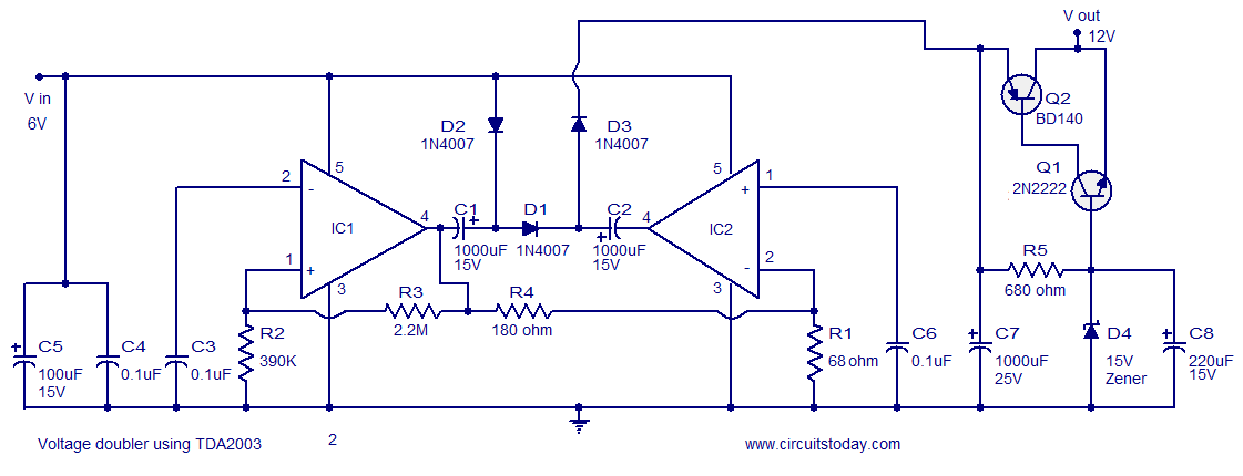
A reliable voltage converter circuit that operates between 6 to 12 volts, utilizing the audio amplifier IC TDA 2003. This voltage doubler circuit can be assembled on a Vero board. The voltage converter circuit designed with the TDA 2003 audio...
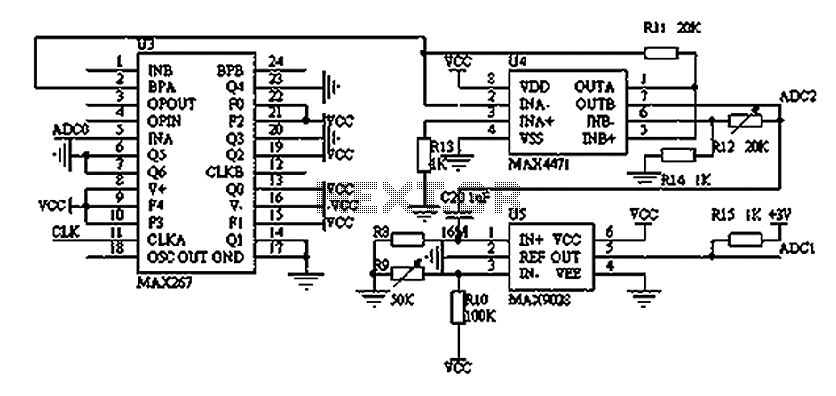
The filtering and amplifying circuit consists of two main components. The MAXIM MAX267 filter is an integrated circuit that can function as a low-pass, band-pass, high-pass filter, and other configurations, offering superior performance compared to traditional op-amp filters. The...
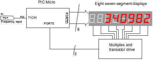
The circuit employs a straightforward approach for direct frequency measurement, which is user-friendly but results in the number of displayed digits varying with the input frequency. To consistently display all digits, a method known as reciprocal counting can be...
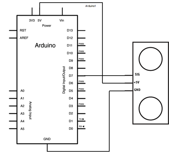
The Ping is an ultrasonic range finder from Parallax. It detects the distance of the closest object in front of the sensor (from 2 cm up to 3 m). It works by sending out a burst of ultrasound and...
Warning: include(partials/cookie-banner.php): Failed to open stream: Permission denied in /var/www/html/nextgr/view-circuit.php on line 713
Warning: include(): Failed opening 'partials/cookie-banner.php' for inclusion (include_path='.:/usr/share/php') in /var/www/html/nextgr/view-circuit.php on line 713