
how to build water level indicator
The described circuit functions as a water level monitoring system, employing a microcontroller and a simple comparator setup to provide real-time feedback on water levels. The use of steel rods as sensors allows for effective detection of water levels, with the circuit designed to minimize power consumption during idle periods. The choice of components ensures reliability and ease of assembly, making it suitable for various applications beyond metal tanks. The remote unit's design emphasizes the importance of insulation and minimal current draw, which is crucial for battery-operated systems. The flexibility in cable type and length enhances installation options, allowing for adaptability in different environments. The ability to modify the system for non-metal tanks by adding an additional sensor rod showcases the circuit's versatility. Overall, this project exemplifies an efficient solution for remote water level monitoring, with potential applications in residential and industrial settings.The whole project was developed on a friend`s request. Its purpose was to remotely monitor the water-level in a metal tank located in the attic by means of a very simple control unit placed in the kitchen, some floors below. Mains requirements were: The very small remote unit is placed near the tank and measures the water level in three ranges by
means of two steel rods. Each range will cover one third of the tank capacity: When the water-level is below the steel rods, no contact is occurring from the metal can and the rods, which are supported by a small insulated (wooden) board. The small circuit built around IC1 draws no current and therefore no voltage drop is generated across R5.
IC2A, IC2B and Q1 are wired as a window comparator and, as there is zero voltage at input pins #2 and #5, D3 will illuminate. When the water comes in contact with the first rod, pin #13 of IC1 will go high, as its input pins #9 to #12 were shorted to negative by means of the water contact.
Therefore, R4 will be connected across the full supply voltage and the remote circuit will draw a current of about 9mA. This current will cause a voltage drop of about 0. 9V across R5 and the window comparator will detect this voltage and will change its state, switching off D3 and illuminating D2.
When the water will reach the second rod, also pin #1 of IC1 will go high for the same reason explained above. Now either R3 and R4 will be connected across the full supply voltage and the total current drawing of the remote circuit will be about 18mA.
The voltage drop across R5 will be now about 1. 8V and the window comparator will switch off D2 and will drive D1. The battery will last very long because the circuit will be mostly in the off state. Current is needed only for a few seconds when P1 is pushed to check the water-level and one of the LEDs illuminates. The two-wire cable connecting the remote circuit board to the main control board, i. e. J1 to J2, can be of any size and type (preferably thin for obvious reasons). It can be very long, if necessary. The circuit can be used also with non-metal tanks, provided a third steel rod having the height of the tank will be added and connected to pin #7 of IC1, R3, R4 and J1.
The 4012 chip was chosen because it contains two gates and was at hand, but you can use two of the gates contained into 4001, 4011, 4093, 4049, 4069 etc. chips, provided all inputs of each gate are tied together and all inputs of unused gates are connected to the positive rail, leaving output pins open.
🔗 External reference
Related Circuits
An analog VU meter is commonly found in audio equipment to indicate signal levels in volume units. It features a peak LED and compares the response of the VU meter (represented by a black line) with the instantaneous input...
The article describes the process of building a charger controller board and programming the AVR microcontroller. A Li-Ion battery is needed for practice; the example battery mentioned has withstood considerable abuse. Knowledge of the battery's specifications, such as maximum...
A UHF indicator, or wavemeter, is a device that measures frequencies and determines the resonance frequency of an LC circuit. This device operates without the need for radiation. The oscillator is constructed using transistors T1 and T2 (two BF494),...
Since the volume control is after the gain stage, the preamp can be easily overloaded. I tried to limit the input signal by mounting a 470 k resistor in series with the CD input. A voltage divider is formed...
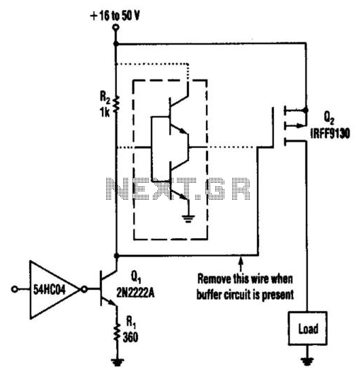
This circuit operates from a 16- to 50-V supply. Adding the buffer circuit (within the dashed lines) offers 100-ns switching times. Otherwise, the circuit switches in 1 µs. Q1 and R1 form a switched current source of about 12...
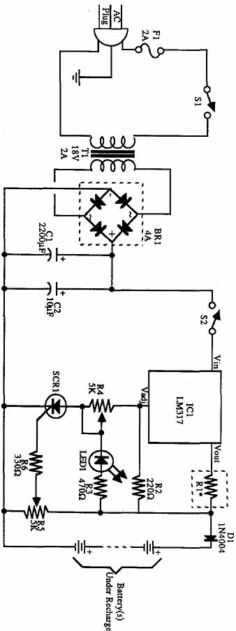
The incoming AC is routed to the primary terminals of a 12.6-volt transformer. The hot side of the AC is connected through a fuse and a single-pole single-throw (SPST) toggle switch. When the switch is in the OFF position,...