
Audio level meter circuit - VU Level Meter

The audio level meter circuit, commonly referred to as a Volume Unit (VU) meter, serves the purpose of visually displaying the amplitude of audio signals. It typically employs a series of transistors configured to amplify the incoming audio signal, allowing for accurate representation of sound levels across a broad frequency spectrum.
The circuit design includes a basic input stage where the audio signal is fed. This signal is then processed through a transistor-based amplifier, which boosts the signal to a level suitable for driving the meter. The transistors used in the circuit are selected for their linear characteristics, ensuring a flat frequency response from 20Hz to 50kHz. This range covers the majority of audible frequencies, making the VU meter effective for various audio applications.
The output of the amplifier is connected to a needle or LED display that provides a visual indication of the audio level. The display is calibrated to reflect the intensity of the signal, allowing users to monitor audio levels in real-time. Additional components such as resistors and capacitors are included to filter noise and stabilize the circuit operation, ensuring reliable performance.
This audio level meter circuit is ideal for use in audio mixing environments, public address systems, and recording studios, where precise audio level monitoring is crucial for achieving optimal sound quality. The schematic diagram accompanying the circuit provides a clear representation of the connections and component values necessary for assembly.A simple audio level meter or a Volume unit VU level meter circuit with diagram and schematic. This sound level meter is designed using transistors with a flat frequency response in the range of 20Hz to 50Khz.. 🔗 External reference
Related Circuits
This 10-band graphic equalizer circuit utilizes a single chip, the IC TL074, to create a 5-band graphic equalizer suitable for high-fidelity audio systems. The 5-band graphic equalizer is particularly effective for radio-cassette players and car stereos. Key features include...

It is embarrassing to acknowledge that the blog post from April 29 contained several schematic errors of my own making, particularly in the variation of Morgan Jones's circuit. One of the resistor values was incorrect by a factor of...
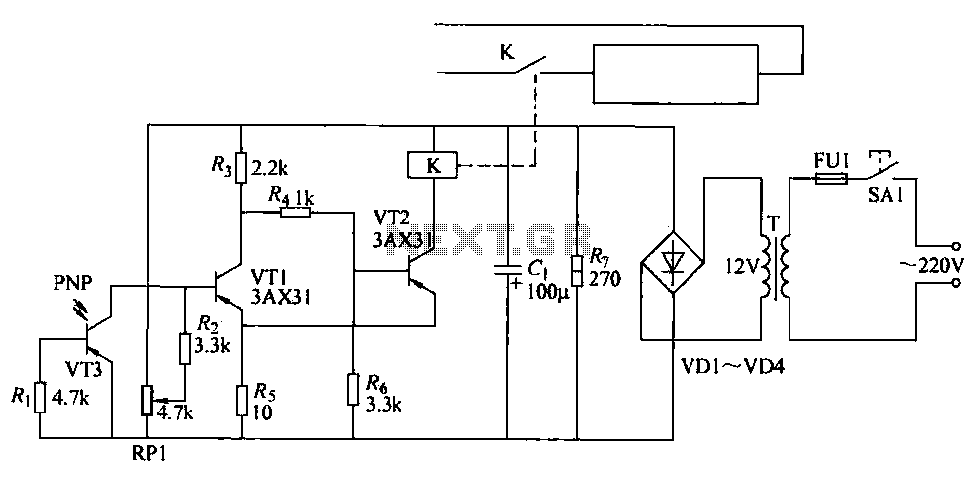
The cutter is safeguarded by a printed circuit phototransistor designed to prevent accidental activation of the cutter switch during manual feeding. In the event of manual feeding, the automatic paper cutter can be controlled to shut down. A relay...
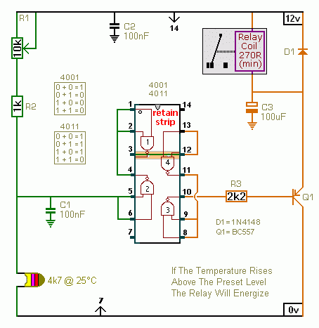
A CMOS 4001 or a CMOS 4011 can be utilized in this circuit, as both contain four two-input gates. The inputs of each gate are connected together, allowing them to function as simple inverters. This means that when both...
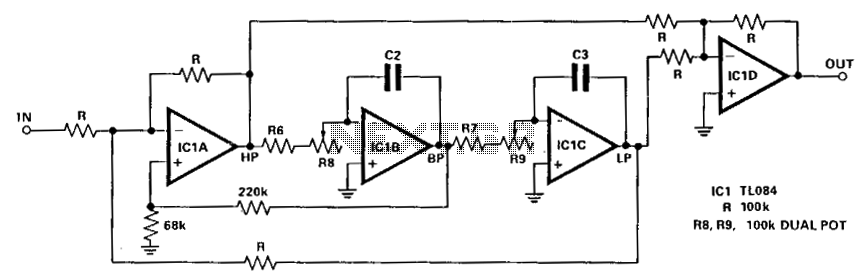
The circuit illustrated here demonstrates that the response at one octave off-tune remains within 10% of the far-out response. The sharpness of the notch can be adjusted by increasing or decreasing the 68-ohm resistor. The linearity tracking of resistors...
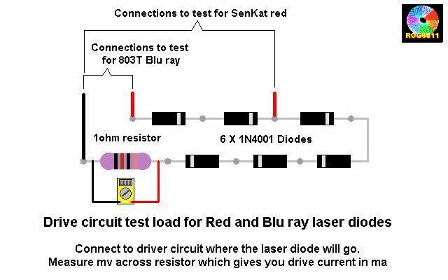
A guide will be posted on how to test a DDL circuit before integrating the LD. The process aims to ensure clarity and accuracy throughout. To properly test a DDL (Direct Drive Laser) circuit before adding the LD (Laser Diode),...