
Auto Cutter mill circuit
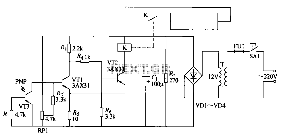
Working Principle: The first and second transistors form an emitter-coupled flip-flop. When a worker's hand obstructs the light from the bulb, the phototransistor shows high resistance, causing a change in voltage that turns off the second transistor. This deactivates the relay coil, opening the normally open contact and interrupting the current path to the cutter knife operation control coil. This design effectively prevents the cutter from operating when a worker's hand is in the vicinity, thereby minimizing the risk of accidents during manual paper feeding.
The circuit design incorporates a phototransistor (VT3) that detects the presence of light from a bulb. When a worker's hand covers the bulb, the light is obstructed, leading to a high-resistance state in the phototransistor. This change in resistance alters the voltage levels in the circuit, which is crucial for the operation of the flip-flop configuration formed by transistors VT1 and VT2.
Transistor VT1 is configured to respond to the signal from the phototransistor. When the light is blocked, VT1 turns off, which subsequently results in the deactivation of VT2. The relay (K) that controls the cutter operation is connected to the collector of VT2. In its normal state, with sufficient light, the relay remains energized, allowing the cutter to function. However, once the relay coil is deactivated due to the signal from the phototransistor, the normally open contact (KA1) opens, cutting off the current path to the cutter knife.
This safety mechanism is crucial in environments where manual feeding is common, as it ensures that the cutter does not operate inadvertently, thus protecting workers from potential injuries. The careful arrangement of components, including the light source, phototransistor, and relay, exemplifies effective design practices in electronic safety circuits.Cutter is protected by a printed circuit phototransistor constructed to prevent manual feeding mistakenly stepped on the cutter switch and cause accidents. The line at the time of manual feeding, automatic paper cutter can be controlled shutdown. Relay has a normally open contact K series cutter knife in operation control coil power supply circuit, only when the normally open contact K is closed, the next paper cutter before knife. K relay coil connected in series with the collector VT2 circuit, controlled by the state of VT2, VT2 and VT1 controlled by, VT1 by the phototransistors controlled VT3, VT3 controlled by light.
Cutter mounted in the side of the bulb to the other side of the exposure. lrf3 mounted on the other side with the received light bulbs to light.. Working principle: VT1 and VT2 can be composed of an emitter coupled to flip-flop. When workers hand put paper, hand it will cover light bulbs to light, so VT3 phototransistor showed high resistance, and thus will make Vn conduction, VT2 off, KA relay coil power release, its normally open contact point KA1 reset off so cutter knife operation control coil current path is cut off, to prevent release cutter workers hand cut paper when the accident occurred.
Related Circuits
CD4060 Timer Circuit 1 minute to 2 hours This is a 1 minute to two-hour timer switch. The 14-stage binary ripple counter Type 4060, IC1, has an... The CD4060 timer circuit is designed to function as a timer switch with...
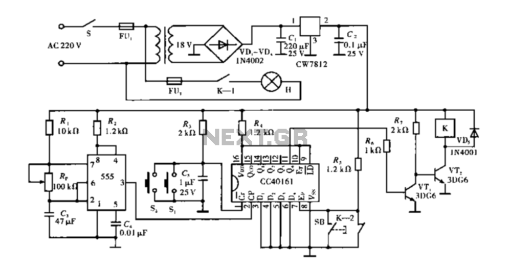
Corridor counter delay circuit for controlling lights. This circuit is tested and functional. When the circuit is energized, the 555 oscillator starts to oscillate. The CC40161 is cleared, and an integrating circuit composed of R3 and C5 transitions the...

This circuit produces a soft turn-on for halogen lamp filaments upon powering up. The MOSFET used is a BUZ10, which has a resistance of 0.2 ohms. Resistors R1, R2, and capacitor C1 set the turn-on rate, while diode D1...
The chart illustrates a clock designed for a competition, utilizing a 555 timer circuit. This circuit is characterized by its novel design, reliable performance, ease of assembly, and engaging functionality. The 555 timer is available in two types: bipolar...
This is a simple magnetic levitation circuit that suspends objects at a specified distance below an electromagnet. The underlying physics involves providing a magnetic force that counteracts gravity. The magnetic levitation circuit operates by utilizing an electromagnet, which generates a...
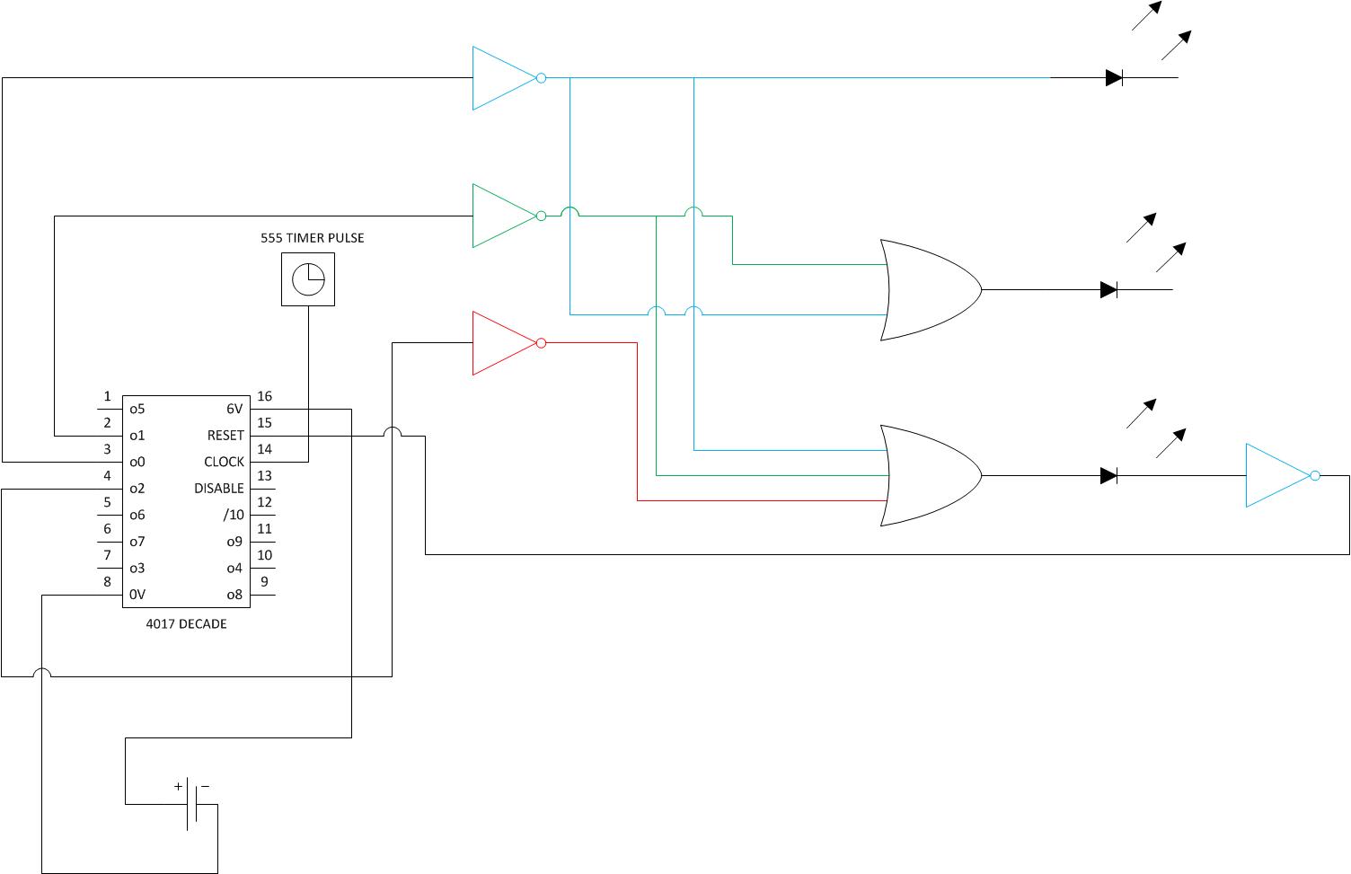
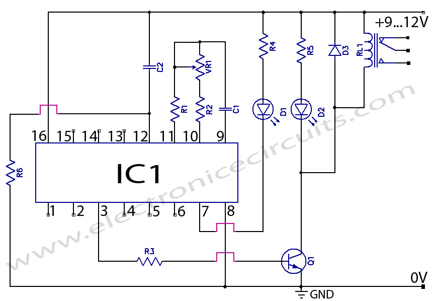
The goal is to create a timer activated by a button press, which will light three LEDs. After each 5-minute segment, one LED should turn off. After 15 minutes, a solenoid should ring a bell once. The individual has...