
testing ddl s circuit
To properly test a DDL (Direct Drive Laser) circuit before adding the LD (Laser Diode), several steps must be followed to ensure the circuit functions correctly and safely.
1. **Preparation**: Gather necessary tools including a multimeter, oscilloscope, power supply, and appropriate test loads. Ensure that all components are rated for the specifications of the DDL circuit.
2. **Visual Inspection**: Begin with a thorough visual inspection of the circuit board and components. Look for any signs of damage, such as burnt traces, cracked components, or incorrect solder joints. Ensure that all components are properly placed according to the schematic.
3. **Power Supply Check**: Before applying power, verify that the power supply voltage matches the specifications of the DDL circuit. It is critical to ensure that the polarity is correct to prevent damage.
4. **Initial Testing**: Power the circuit without the LD connected. Measure the voltage at various points in the circuit with a multimeter to ensure that the expected voltages are present. This includes checking the supply voltage and any reference voltages required by the circuit.
5. **Signal Testing**: Use an oscilloscope to analyze the output signal of the circuit. Check for the correct waveform shape and frequency. This step is crucial to confirm that the circuit is generating the appropriate signals to drive the LD once it is connected.
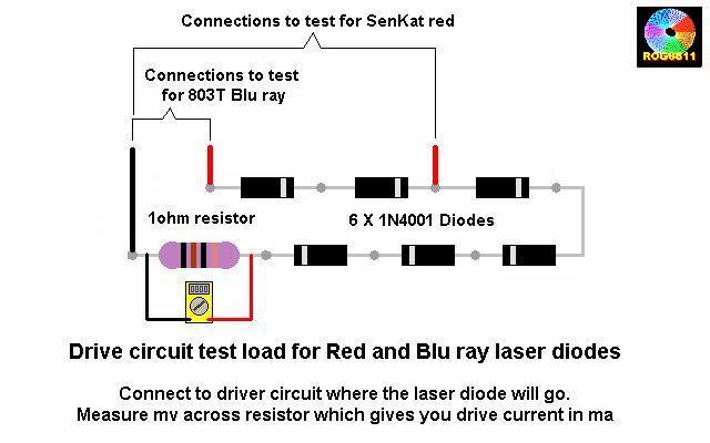
6. **Load Testing**: If the circuit includes a test load, connect it and observe the circuit's behavior under load conditions. Monitor for any fluctuations in voltage or current that may indicate issues within the circuit.
7. **Final Verification**: After all tests have been completed and the circuit has been confirmed to be functioning correctly, it is safe to proceed with integrating the LD. Ensure that the LD is correctly oriented and connected according to the schematic.
By following these steps, the DDL circuit can be effectively tested to ensure reliability and performance prior to the addition of the laser diode. This process helps prevent potential damage to the LD and ensures optimal operation of the entire system.I am about to post a How To on testing DDL`s circuit before adding the LD, I hope it is all pretty clear and with no errors. Those .. 🔗 External reference
Related Circuits
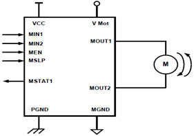
The schematic presented illustrates a 5A H-Bridge Module designed for the operation of a single Bipolar DC motor. The H-Bridge Module includes a header set (J2) and a connector terminal set (J1). Below is the pinout description for the...
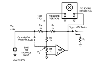
The diagram below illustrates a classic test fixture that has been utilized for an extended period to assist individuals in addressing non-linearity errors. The classic test fixture depicted in the diagram serves as a fundamental tool in electronics testing and...
This circuit utilizes two operational amplifiers (op-amps) to create a unique sound effect. The first op-amp, CA741, is configured as a standard astable multivibrator, generating timing pulses controlled by components C1, R2, and variable resistor VR1. The output from...
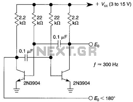
This free-running square-wave oscillator utilizes two NPN transistors. The output frequency is approximately 300 Hz with the specified component values. The circuit operates as a basic oscillator, generating a square wave output through the interaction of two NPN transistors. The...
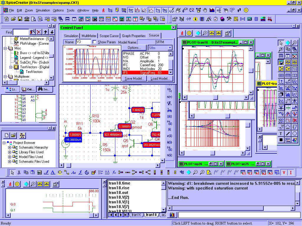
Circuit CREATOR Electronics CAE System provides the most complete and high performance solution for electronics design using personal computers. More: Includes PCB DESIGN -layout editor and Schematic Capture software tool, full Schematic Design and Capture, Circuit Simulation, full interactive...
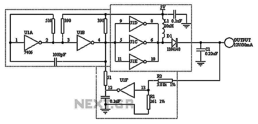
A TTL hex inverter circuit can function as a DC/DC converter, converting 5V to 12V. This circuit encompasses all necessary functionalities for DC/DC conversion. It relies on a TTL switching threshold voltage regulator. The components U1A and U1B form...