
Audio Light Modulator circuit
The described circuit is designed to create an engaging audio-visual experience by modulating light in response to audio signals. The core function of this circuit is to take a small portion of the audio output from an audio amplifier and use it to control a light source, such as an LED or a lamp, effectively synchronizing light patterns with the audio output.
The audio signal from the speaker terminals is coupled to the circuit through a non-polarized capacitor, which serves to block any DC component while allowing the AC audio signal to pass. This is crucial for ensuring that only the audio frequencies affect the light modulation, preventing any potential DC offset from interfering with the operation of the circuit.
A transformer is incorporated into the circuit to provide electrical isolation between the audio amplifier and the light modulation circuit. This isolation is important for safety, as it minimizes the risk of shock from the mains voltage, which can be present in the circuit. The transformer steps down the audio signal to a manageable level suitable for processing by the subsequent components.
The sensitivity control potentiometer, designated as VR1, is strategically placed in the circuit to allow for adjustment based on the audio source level. By tuning this potentiometer, the user can set a threshold level for audio frequency detection, ensuring that the light modulation only activates when the audio signal exceeds a certain amplitude. This feature enhances the responsiveness of the circuit to dynamic changes in audio levels, making it more effective for various music genres and volume settings.
Furthermore, the circuit includes a diode bridge that converts the AC signal from the transformer into pulsating DC. This pulsating DC can be used to drive the light source, creating a flickering effect that corresponds to the audio input. The diode bridge also serves as a protective measure, providing a safeguard between the mains input and the pulsating DC output, thus protecting sensitive components from voltage spikes or surges.
Proper earthing of the circuit is emphasized as a critical safety measure. It is essential to ensure that all components are correctly grounded to prevent any potential electric shock hazards, especially given that the circuit interfaces with mains voltage.
In summary, this audio light modulation circuit effectively combines audio signals with light control, creating an immersive experience while prioritizing safety through isolation and proper electrical design practices.Audio light modulations add to the enjoyment of music during functions organised at home or outdoors. Presented here is one such simple circuit in which light is modulated using a small fraction of the audio output from the speaker terminals of the audio amplifier.
The output from the speaker terminals of audio amplifier is connected to a transformer (output transformer used in transistor radios) through a non-polarised capacitor. The use of transformer is essential for isolating the audio source from the circuit in The sensitivity control potentiometer VR1 provided in the input to transistor T1 may be adjusted to ensure that conduction takes place only after the AF exceeds certain amplitude.
This control has to be adjusted as per audio source level. The audio signal Proper earthing of the circuit is quite essential. The diode bridge provides pulsating DC output and acts as a guard circuit between the mains input and pulsating DC output. Extreme care is necessary to avoid any electric shock. 🔗 External reference
Related Circuits
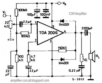
The power amplifier IC TDA2006 provides high output current and has very low harmonic and cross-over distortion. Furthermore, the device incorporates an original (and patented) short circuit protection system that automatically limits the dissipated power to keep the working...
The circuit receives its input from the zero-crossing detector, which generates a 0-to-1-to-0 pulse to set the R-S flip-flop and activate the ramp circuit (A to Ramp) to initiate the timing ramp ascent. The described circuit operates by utilizing a...
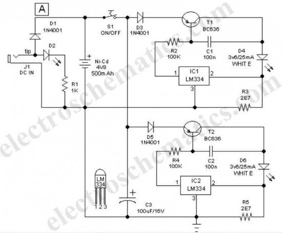
This easy-to-construct handy pen torch electronic circuit features a low component count and utilizes two power white LEDs for illumination. A low voltage (4.8V DC) supply is sourced from a built-in rechargeable Ni-Cd battery pack, which is converted into...

The three-channel amplifier output distribution uses a single TL084. The first step is to capacitive coupling with a 1.0 µF electrolytic capacitor. The entries are railways Vee Y2 or 4.5 V. This allows using a single 9 V power...

The SX 28 internal oscillator is not that fast, so an external oscillator can be hooked up to the processor as shown in the diagram to increase the operation cycles per second. The SX 28 microcontroller is designed with an...

A 3D enhancement is required to achieve a fully three-dimensional sound experience for most stereo multimedia products. Typically, simple phase-delay circuits are utilized to create a widening effect on the perceived sound field. However, this approach can lead to...