
Handy Pen Torch circuit
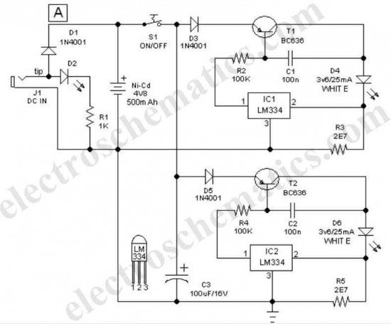
The handy pen torch circuit is designed for simplicity and efficiency, making it an excellent project for electronics enthusiasts. The use of LM334 chips allows for precise current regulation, ensuring that the power white LEDs operate within their optimal range, thus maximizing brightness while extending their lifespan. The choice of a rechargeable Ni-Cd battery pack is practical, providing a reliable power source that can be easily replaced or recharged.
The circuit's design also emphasizes safety features, such as the inclusion of diode D1, which protects the battery from potential damage caused by reverse current flow. The compact nature of the circuit allows it to be housed in a small enclosure, enhancing portability and usability. The incorporation of a simple AC mains-powered charger further adds to the convenience, allowing users to recharge the battery without the need for specialized equipment.
The overall architecture of the circuit is straightforward, making it accessible for hobbyists and students looking to deepen their understanding of LED drivers, constant current sources, and battery charging techniques. This project not only provides practical experience in circuit assembly and soldering but also offers insights into the principles of power management in electronic devices.This easy to construct Handy pen torch electronic circuit and low component count, uses two power white LEDs for lighting. Low volt (4. 8V dc) supply available from the built in rechargeable Ni-Cd battery pack is first converted into two channel (independent) constant current sources by two pieces of the renowned precision adjustable shunt regul
ator chip LM334 (IC1 and IC2). Around 25 mA at 3. 6 volt dc is available at the output of these ICs. This regulated dc supply is used to drive two power white LEDs D4 and D6. Resistors R3 and R5 limlits the output current (and hence the light output) of IC1 and IC2 circuits respectively. Diode D1 works as an input polarity guard cum reverse current flow preventer. Capacitor C1 is a simple buffer for circuit stabilization. After succesful construction, preferably on a small piece of general purpose PCB, enclose the whole circuit in a suitable and attractive pen torch cabinet.
If necessary, drill suitable holes in the cabinet to attatch the dc socket, on/off switch and the input indicator etc. In prototype, commonly available 4. 8 volt/500mah Ni-Cd battery pack (for cordless telephones) is used. One very simple but reliable ac mains powered battery charger circuit for the handy pen torch is also included here.
Basically the pen torch circuit is a constant current chargerwired around Transistor T1 (BC636), powered by a 12v/350mA step down transformer and associated componentsD1, D2 and C1. Unregulated 12 volt dc available from the input power convereter circuit, comprising step down transformer(TRF), rectifier diodes (D1, D2) and filter capacitor (C1), is fed to T1 through a current limiting resistor R1.
Grounded base PNP transistor T1 here works as a constant current generator. With 22 ohm resistor for R1, the charging current available at the output of the charger is near 50 mA. Red LED (D3) provides a fixed voltage reference to the base of T1, with the help of resistor R2. (During charging process, Diode D1 in the main circuit prevent reverse current flow from the battery pack when charging input supply is absent.
) After construction of the pen torch circuit, fit the assembled unit inside a small plastic enclosure for safety and convenience. We aim to transmit more information by carrying articles. Please send us an E-mail to wanghuali@hqew. net within 15 days if we are involved in the problems of article content, copyright or other problems.
We will delete it soon. 🔗 External reference
Related Circuits
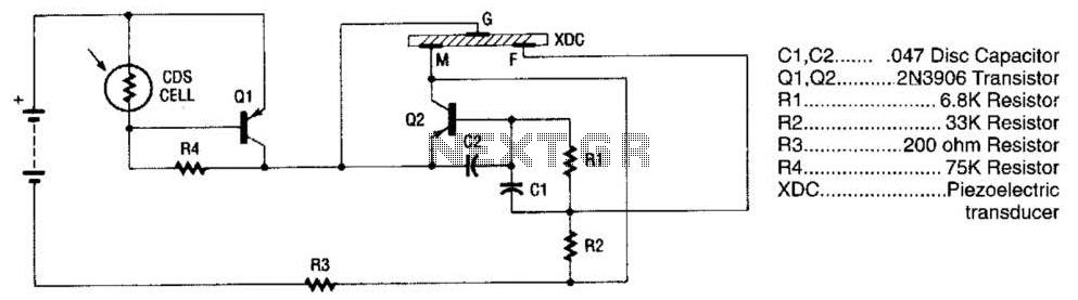
The alarm utilizes a fixed-frequency piezoelectric buzzer alongside a cadmium-sulfide (CDS) cell and a two-transistor circuit to create a distinctive effect. When light reaches the CDS photoelectric cell, the alarm remains silent. However, in the absence of light, transistor...
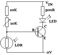
A Light Dependent Resistor (LDR), also known as a photoconductor, photoresistor, or photocell, is a commonly used electronic component that exhibits a decrease in resistance as the intensity of light striking its surface increases, and vice versa. Typically, LDRs...
The circuit operates based on a principle where the SCR (Silicon Controlled Rectifier) trigger is grounded, keeping it in the off state. When a burglar triggers the alarm, a voltage is supplied to the SCR trigger, turning it on....

This design circuit illustrates an LM1893 power line modem circuit. It is utilized to transfer information between remote locations using the power mains. The circuit employs the LM1893, which functions as a power line interface for half-duplex (bi-directional) communication...
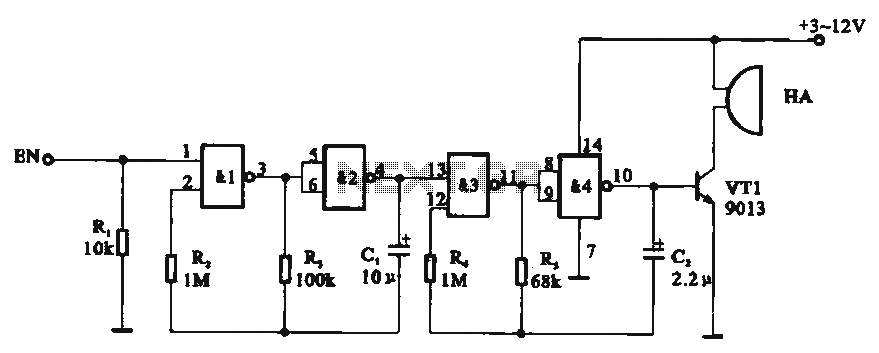
Tone generator circuit. The tone generator circuit utilizes a quad 2-input NAND gate integrated circuit, specifically the CD4011. NAND gates 1 and 2, along with NAND gates 3 and 4, form two gating multivibrator oscillators. The oscillation period of...
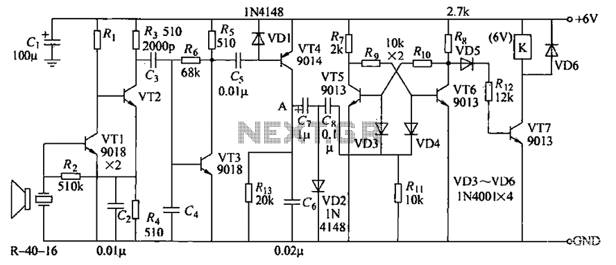
The circuit consists of transistors VT1 through VT7 and other components. Due to the weak signal received from the transmitter, the circuit employs a multi-stage amplifier to enhance the output. This output generates a square wave pulse signal to...
Warning: include(partials/cookie-banner.php): Failed to open stream: Permission denied in /var/www/html/nextgr/view-circuit.php on line 713
Warning: include(): Failed opening 'partials/cookie-banner.php' for inclusion (include_path='.:/usr/share/php') in /var/www/html/nextgr/view-circuit.php on line 713