
Phase Delay Network for 3D Audio Enhancement

More: Simple phase-delay circuits are active circuits that employ a first-order section to implement a phase-shift filter with a cutoff frequency (ft) of 1 kHz for the quadrature signal and a cutoff frequency of 10 kHz for the linear signal. This configuration produces a 90° phase shift between the quadrature and linear signals across the audio bandwidth of 1 kHz to 10 kHz.
The implementation of a 3D audio enhancement circuit involves the careful design of phase-delay circuits that significantly contribute to the perception of spatial audio. The circuit typically consists of a combination of operational amplifiers configured to create the necessary phase shifts for both quadrature and linear signals.
The first-order phase-shift filter is crucial in this design, as it allows the audio signals to be manipulated effectively within the specified frequency range. The choice of cutoff frequencies—1 kHz for the quadrature signal and 10 kHz for the linear signal—ensures that the circuit can handle the typical audio bandwidth while maintaining clarity and fidelity.
The output of the phase-delay circuit is then combined to produce a stereo output that enhances the spatial characteristics of the audio. By introducing a 90° phase shift, the circuit effectively widens the sound field, creating an immersive listening experience that simulates a three-dimensional sound environment.
However, careful consideration must be given to the transaural acoustic crosstalk effect, which can occur when audio signals intended for one ear are inadvertently heard by the other ear. This phenomenon can detract from the desired 3D effect and requires additional measures, such as crosstalk cancellation techniques or advanced filtering, to mitigate its impact.
Overall, the design of a 3D enhancement circuit using simple phase-delay circuits is a sophisticated endeavor that combines principles of audio engineering and psychoacoustics to deliver a compelling auditory experience.3D enhancement is needed to create a fully 3-dimensional sound for most stereo multimedia products. Usually, simple phase-delay circuits is used to produce a widening effect on the perceived sound field. However, there is transaural acoustic crosstalk effect. The following figure shows transaural acoustic crosstalk effect and schematic diagram of simple phase-delay circuits : This is an active circuit that uses first-order section to present a phase-shift filter with ft of 1kHz for the quadrature signal and ft = 10kHz for the linear signal. It will produce 90 ° phase shift between the quadrature and linear signals over the audio bandwidth of 1kHz to 10kHz.
[Source: maxim-ic. com] 🔗 External reference
Related Circuits
The mixer is the common "virtual earth" mixing amplifier, and there is nothing special about it. Note that it is inverting, which complements the tone controls (also inverting) so the absolute signal polarity is maintained. As shown, the mixer...
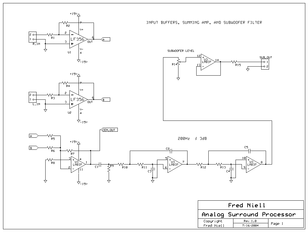
The overall block diagram of the system shows that audio input enters from the left and undergoes various processing steps including summation, differencing, multiplication, delay, and filtering. The output consists of five discrete audio channels along with one low-frequency...
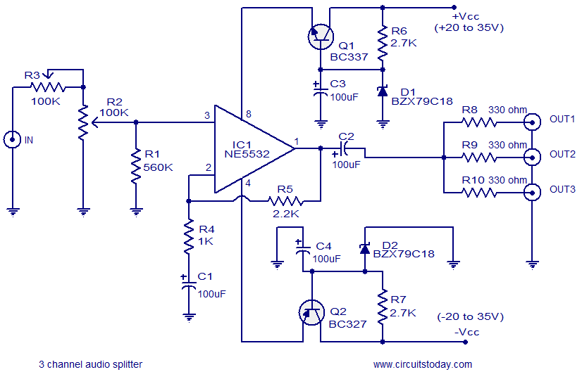
The circuit diagram illustrates a simple 3-channel audio splitter utilizing the NE5532 integrated circuit. The NE5532 is a dual, internally compensated low-noise operational amplifier produced by Fairchild Semiconductors. It features a high small-signal and power bandwidth, making it ideal...
A 20-band equalizer for a 900-watt MOSFET power amplifier. The output level would decrease by the amount of resistors, so for two equal resistors, it should be amplified by a gain of 3. The first schematic is a simple...
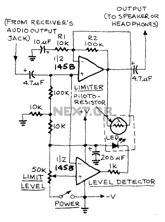
The AUD.LIMITER circuit features a level trim potentiometer that allows for adjustment of the limiting level. When the input signal exceeds the set level of the potentiometer, the output from one half of the operational amplifier, functioning as a...
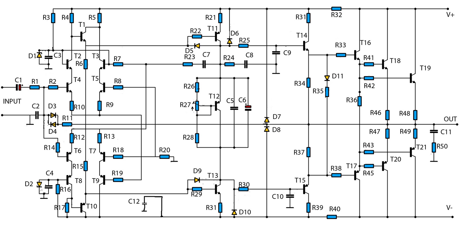
This is a mono amplifier circuit with a high output power of 1400W. It is well-suited for use in large rooms with woofer and full-range speakers, delivering a loud and clear sound with minimal noise. The amplifier utilizes high-quality...