
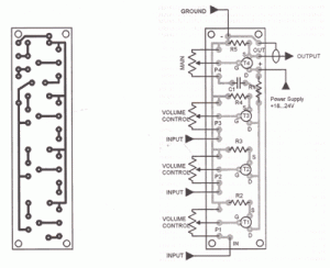
test beeper for audio amplifiers
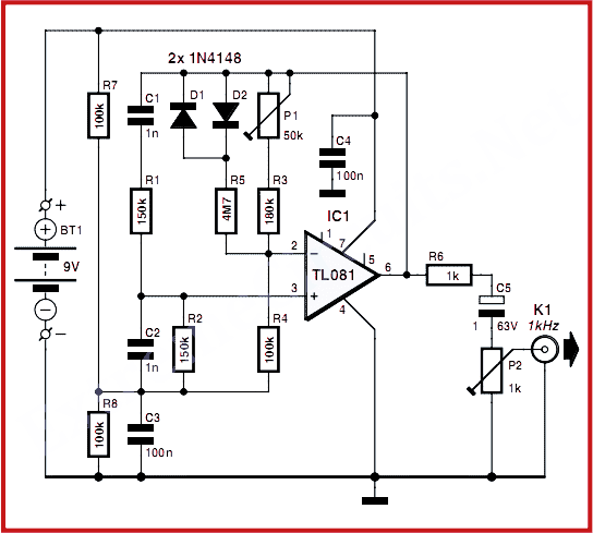
The Wien-Bridge oscillator is a well-established circuit for generating sine waves, particularly in audio applications. Its fundamental operation relies on the balance of resistive and capacitive elements to produce a stable frequency output. In this configuration, R1 and C1 form a series network, while R2 and C2 are arranged in parallel, ensuring that the frequency is determined by the equation f = 1 / (2πRC), where R and C represent the values of the resistors and capacitors used.
The operational amplifier (IC1) plays a crucial role in amplifying the signal produced by the oscillator. The gain setting is vital for sustaining oscillation; thus, the adjustable potentiometer P1 allows for fine-tuning of this gain. The presence of R3 and R4 aids in establishing the feedback loop, which is essential for the oscillator's stability.
The inclusion of diodes D1 and D2 ensures that the output signal remains within acceptable limits, preventing distortion through clipping. This feedback mechanism is particularly advantageous in maintaining a consistent output amplitude, especially under varying load conditions. The circuit's design is optimized for low power consumption, making it suitable for portable applications powered by a 9-V battery, thereby extending operational longevity.
Overall, this test beeper circuit exemplifies a practical implementation of a Wien-Bridge oscillator, offering a reliable and adjustable sine wave output suitable for testing audio equipment.The test beeper generates a sinusoidal signal with a frequency of 1, 000 Hz, a common test frequency for audio amplifiers. It consists of a classical Wien-Bridge oscillator (also known as a Wien-Robinson oscillator). The network that determines the frequency consists here of a series connection of a resistor and capacitor (R1/C1) and a parallel co
nnection (R2/C2), where the values of the resistors and capacitors are equal to each other. This network behaves, at the oscillator frequency (1 kHz in this case), as two pure resistors. The opamp (IC1) ensures that the attenuation of the network (3 times) is compensated for. In principle a gain of 3 times should have been sufficient to sustain the oscillation, but that is in theory. Because of tolerances in the values, the amplification needs to be (automatically) adjusted. Instead of an intelligent amplitude controller we chose for a somewhat simpler solution. With P1, R3 and R4 you can adjust the gain to the point that oscillation takes place. The range of P1 ( ±10%) is large enough the cover the tolerance range. To sustain the oscillation, a gain of slightly more than 3 times is required, which would, however, cause the amplifier to clip (the round-trip` signal becomes increasingly larger, after all).
To prevent this from happening, a resistor in series with two anti-parallel diodes (D1 and D2) are connected in parallel with the feedback (P1 and R3). If the voltage increases to the point that the threshold voltage of the diodes is exceeded, then these will slowly start to conduct.
The consequence of this is that the total resistance of the feedback is reduced and with that also the amplitude of the signal. So D1 and D2 provide a stabilizing function. The distortion of this simple oscillator, after adjustment of P1 and an output voltage of 100 mV (P2 to maximum) is around 0, 1%.
You can adjust the amplitude of the output signal with P2 as required for the application. The circuit is powered from a 9-V battery. Because of the low current consumption of only 2 mA the circuit will provide many hours of service. 🔗 External reference
Related Circuits

At the time, there was a desire to construct an ultimate continuity tester, leading to the creation of a wish list of required features. A genuine continuity tester is needed, as many multimeters and sounders react to resistances as...
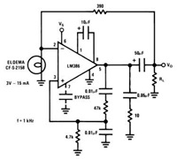
This device has a quiescent power drain of 24 milliwatts when operating from a 6 V supply, making the LM386 ideal for battery operation. According to the application hints section of the LM386 datasheet, two pins (1 and 8)...
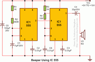
This beeper circuit utilizes two 555 integrated circuits (ICs) and can operate within a supply voltage range of 5 to 15V DC. It is suitable for applications requiring an alarm or beeping signal. The first IC (IC1) is configured...
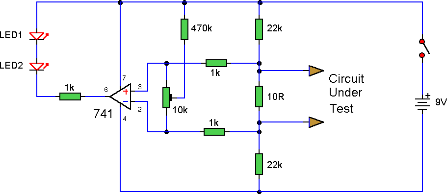
This circuit employs a 741 operational amplifier (op-amp) in differential mode to function as a continuity tester. The voltage difference between the non-inverting and inverting inputs is amplified by the op-amp's full open-loop gain. For the moment, the 470kΩ...

This is a circuit for an audio frequency meter. This circuit utilizes a 555 IC configured as a monostable multivibrator (one-shot trigger). A monostable multivibrator can function as a frequency-to-voltage converter by producing a fixed pulse width, with the...
This FET audio mixer demonstrates the versatility of FETs. Originally designed for high-frequency applications, FETs can also effectively handle audio frequencies, showcasing exceptional performance in this domain. The circuit can accommodate an unlimited number of inputs, provided that the...