
Electronic Fuse / Low Pass Filter
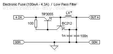
An adjustable electronic fuse serves as a crucial protective device in electrical circuits, designed to prevent damage from overcurrent conditions, such as short circuits or excessive load currents. This particular fuse can be calibrated to operate within a current range of 100 mA to 4.3 A, allowing for flexibility in various applications.
The circuit typically consists of a sensing element, which monitors the current flowing through the load. When the current exceeds the preset limit, the fuse interrupts the circuit to protect the connected devices. The adjustment mechanism may involve a potentiometer or a digital control interface, enabling the user to set the desired current threshold easily.
Key components of the circuit may include a microcontroller or comparator for current sensing, a MOSFET or relay for switching, and additional passive components such as resistors and capacitors for stability and filtering. The design should also incorporate features such as an LED indicator to signal when the fuse has activated or reset.
In terms of layout, the circuit should ensure that the current path is robust enough to handle the maximum load without overheating. Proper heat dissipation techniques, such as heatsinks or thermal pads, may be employed to enhance reliability. Additionally, the fuse should be housed in a suitable enclosure to protect it from environmental factors while allowing for easy access to the adjustment mechanism.
Overall, this adjustable electronic fuse is an essential component for safeguarding power supplies in various electronic applications, ensuring both safety and operational efficiency.This is adjustable elctronic fuse that can be used to protect power supplies from short circuits or can be also used to limit the current usage. It can be adjusted for currents from 100mA up to 4.3A. 🔗 External reference
Related Circuits
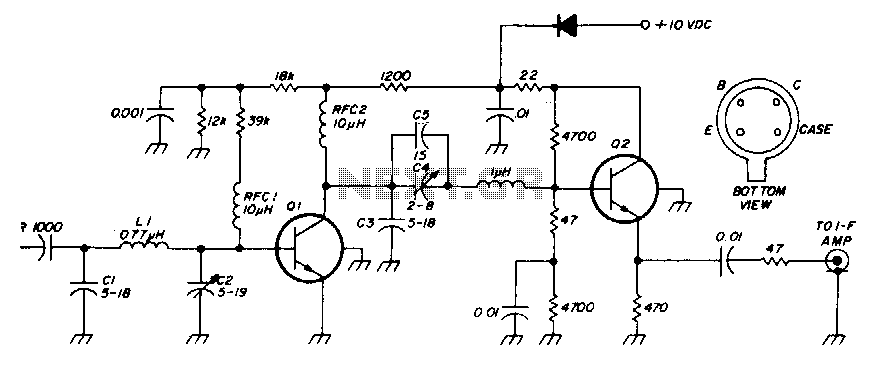
The low-noise preamplifier features a noise figure of 1 dB at 30 MHz and a 3 dB bandwidth of 10 MHz. The gain is 19 dB. The total current drain with a +10 volt supply is 13 mA. The...
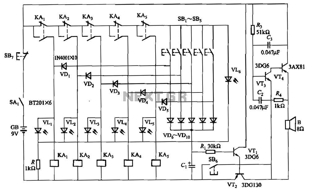
A relay-style circuit designed for a five electronic responder group. This circuit features self-locking capabilities, sound and light displays, time monitoring, and additional functions. The circuit includes a monitoring time button operated by the moderator. When this button is...
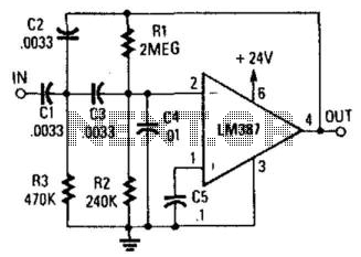
This circuit is a two-section active high-pass filter using an LM387, with a cutoff frequency below 50 Hz at a slope of 12 dB per octave. It will help reduce rumble caused by turntable defects in record systems. The two-section...
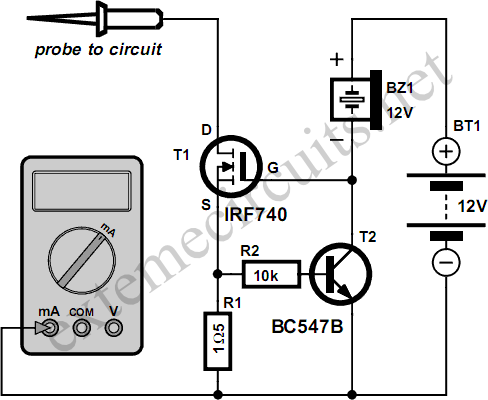
Typically, the input protection fuse of a digital multimeter (DMM) will blow during a demonstration or an exciting phase of construction work. Spare fuses are often difficult to find, and if available, they take a considerable amount of time...
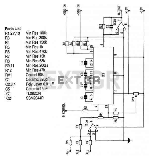
This circuit utilizes the SSM2044 integrated circuit (IC), which is a four-pole voltage-controlled filter specifically designed for electronic music applications. The on-chip voltage control of resonance facilitates straightforward interfacing with programmers and controllers. The IC is characterized by an...
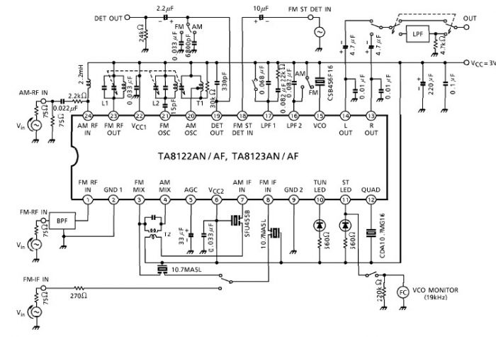
A simple low-power AM/FM radio receiver electronic project can be designed using the TA8122 integrated AM/FM receiver, manufactured by Toshiba Semiconductor. This radio receiver circuit is suitable for portable radio applications or other similar devices. The TA8122 radio receiver...
Warning: include(partials/cookie-banner.php): Failed to open stream: Permission denied in /var/www/html/nextgr/view-circuit.php on line 713
Warning: include(): Failed opening 'partials/cookie-banner.php' for inclusion (include_path='.:/usr/share/php') in /var/www/html/nextgr/view-circuit.php on line 713