
Audio VU Meter using Arduino
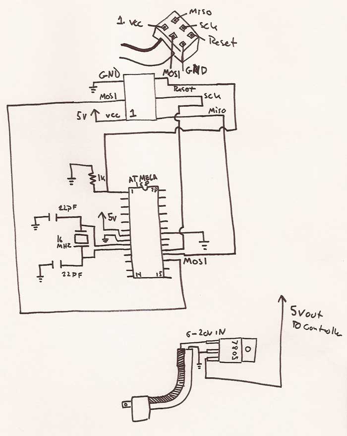
The electronic schematic for this project involves an Atmel microcontroller interfaced with a modified USB speaker system. The main focus is on creating an analog front-end that allows the microcontroller to accurately process audio signals. The circuit should include a rectification stage or a biasing circuit to ensure that the audio signal remains within a safe voltage range for the microcontroller's analog input pins.
The rectification stage can be implemented using a precision rectifier configuration with operational amplifiers, if rectification is chosen. Alternatively, for the DC offset method, a simple voltage divider network can be employed to add a positive bias to the incoming audio signal. This biasing technique would typically involve two resistors and a capacitor to stabilize the DC level while allowing the AC audio signal to pass through.
Once the signal is conditioned, it can be fed into the analog input of the microcontroller. The ADC within the microcontroller will convert the conditioned signal into a digital representation. The sampling rate of 40 kHz ensures that the audio signal is captured accurately, providing sufficient resolution for most audio applications. In the interrupt routine, the ADC conversion is triggered by Timer 1, ensuring that the timing of the sampling is precise and consistent.
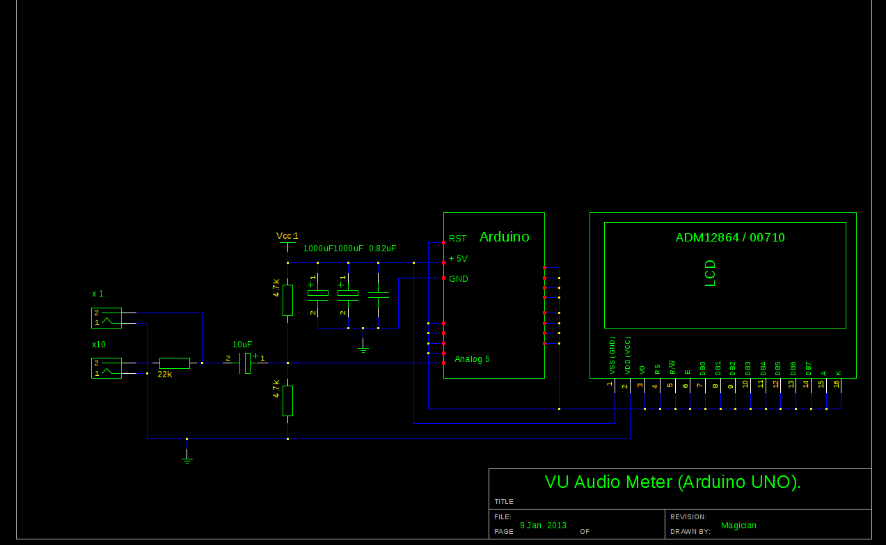
To further enhance the performance, the output from the ADC can be processed using digital signal processing techniques to extract meaningful audio features or to drive visual indicators such as LEDs for audio level monitoring. The entire setup should be powered appropriately, and care must be taken to ensure that the power supply does not introduce noise into the audio signals. Proper grounding and layout practices should be followed to minimize interference and maintain signal integrity throughout the circuit.Hope, you follow my advice and hack your cheap USB speakers, to get nice ( pre-assembled ! ) analog front-end for this project. If not, than get your soldering iron to work, minimum two resistors and 1 cap would required, assuming you already have display wired up and running. First things with AC measurements ( audio in this category ) on Atmel microcontroler is to get rid of negative half-wave of the input signal, and this what front-end circuitry should do. There are at least two option: rectifying AC to DC before voltage could reach arduino analog input, or biasing signal with external DC offset.
Rectification, could nicely be done with help of specifically design IC, LM3914 / 15 / 16 for example. But in this article, I`d describe second alternative, as it`d be not fare to ask you to hack your speakers and than tell you to solder another board .
Here is my set-up, slightly modified version from last blog: When AC input signal is mixed with DC offset, so it stays always in positive area, ( think about sine, which defined betseen -1 and +1, if I add +1 it always would be positive ), I only save arduino life, preventing it from destruction by negative voltage. When arduino ADC completes conversion from analog to digital form, I don`t need DC offset anymore, and it should be subtracted.
2. Sampling subroutine is running at 40 kHz, that is more than enough for ANY application. You may decrease sampling rate to lower CPU load, with current settings VU metering consumes more than 50%. Higher sampling rate gives better linearity / precision over wide band, the same time with regular audio content even 10 kHz sampling would provide better than 1 dB accuracy.
All input capture process goes in Interruption subroutine, which is configured in setup. Two channels of Timer 1 Configured to run in parallel, A is responsible to keep clock at 40 kHz sharp, and B fires start conversion event to ADC with the same speed. Restarting new conversion via hardware provides lowest phase noise compare to any other way of doing this.
🔗 External reference
Related Circuits
A five-band graphic equalizer utilizing a single integrated circuit (IC). The BA3812L is a five-point graphic equalizer that incorporates all necessary functions within its design. The BA3812L is an integrated circuit specifically designed for audio applications, particularly for graphic equalization...
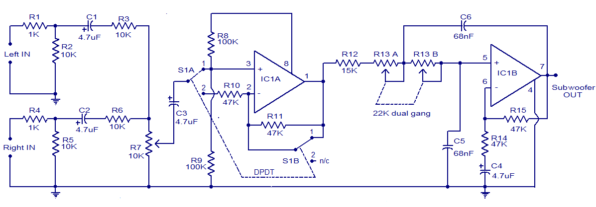
The circuit diagram depicts a simple and effective subwoofer filter designed to operate from a 12V DC supply. This circuit is particularly useful in car subwoofer applications. It functions as a low-pass filter with an adjustable pass frequency ranging...
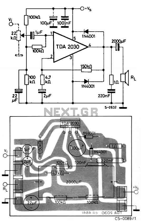
The circuit utilizes the TDA2030, a monolithic integrated circuit housed in a Pentawatt package, designed for use as a low-frequency class AB amplifier. It typically delivers 14W of output power (with a distortion factor of 0.5%) at 14V with...
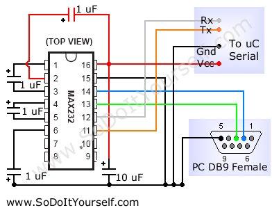
A device that provides a USB port is recognized as a "CP2103 USB to UART Bridge Controller" when connected to a Windows PC. According to the device documentation, it communicates in serial format at 38400 bps. The USB pinout...
One yet circuit with the known LM3915. It does not differ in a lot of points from other applications with same IC. The circuit accosted in those who they want a Vumeter that will be connected in the exit...
The Arduino library can be utilized with other Integrated Development Environments (IDEs) to enhance code organization, particularly for extensive projects. This approach facilitates the integration of code not specifically designed for Arduino and serves as a pathway to more...