
Relay Coil Energy Saver
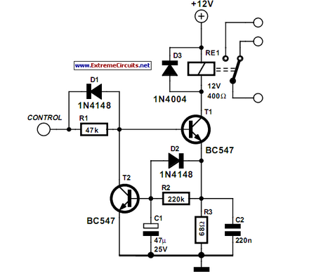
The described circuit addresses the issue of heat generation in relays due to prolonged energization. In typical applications, relays are used to control high-power devices, and when they are continuously energized, they can generate excessive heat, potentially leading to premature failure. The proposed circuit operates by initially energizing the relay to close the contacts, allowing current to flow to the load. After a predetermined time, the circuit reduces the hold current required to keep the relay in the energized state.
This is typically accomplished through the use of a resistor or a secondary control mechanism that modifies the current flowing through the relay coil after the initial actuation. The circuit may incorporate a timing element, such as a capacitor and resistor combination, or a dedicated timing IC, to provide a delay before the hold current is reduced.
The design must ensure that the relay remains in a closed position while the load is powered, even with the reduced current. This can be achieved by utilizing a latching mechanism or a relay with a low holding current specification. Additionally, it is essential to select a relay that can withstand the initial inrush current without damage and to calculate the resistance value for the hold current accurately to ensure reliable operation without risking relay dropout.
In summary, this circuit effectively manages the thermal characteristics of the relay during operation, enhancing reliability and longevity while maintaining functionality in controlling the connected load. Proper component selection and timing considerations are crucial in achieving the desired performance and preventing overheating.Some relays will become warm if they remain energized for some time. The circuit shown here will actuate the relay as before but then reduce the ‘hold cu.. 🔗 External reference
Related Circuits
This sensitive circuit functions primarily as a comparator, capable of detecting minimal temperature changes relative to ambient temperature. It was originally designed to identify drafts around doors and windows that lead to energy loss, but it can be utilized...
Control a toy car. The toy car is operated via a wired controller, rather than being radio-controlled. The intention is to utilize relays to control the toy through a parallel port. There are various types and models of relays,...
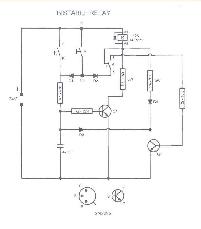
This circuit could be used to drive a monostable relay by a single momentary switch. Powered by 24 Volts, it works for a 12 Volts relay. When the button is pressed, Q1 is energized and the capacitor charges, while...
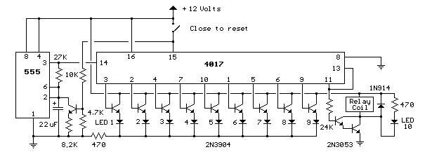
This circuit provides a visual 9-second delay using 10 LEDs before closing a 12-volt relay. When the reset switch is closed, the 4017 decade counter resets to the 0 count, illuminating the LED driven from pin 3. The 555...
The primary advantage of a solid-state relay (SSR) over a traditional electromagnetic relay (EMR) is its reduced wear and tear, which enhances its longevity. The S201S01 model from Clear-Cut serves as an exemplary representation of this technology. The following...
Tesla constructed the world's most powerful radio transmitter. Surrounding the base of a 200-foot mast, he installed an air-core transformer that measured 75 feet in diameter. The primary winding consisted of only a few turns of wire, while the...