
Class D Audio Amplifier Design TDA7498
The circuit design and implementation of audio amplifiers using Class-D technology require careful attention to component selection and layout to achieve optimal performance. The TDA7498 chip, designed for high-efficiency audio amplification, operates on a switching principle that allows for reduced power consumption while maintaining sound quality. However, the performance of such amplifiers is heavily influenced by the choice of passive components, particularly capacitors within the signal path.
In the case of the Sure Electronics TDA7498 PCB, the initial choice of ceramic capacitors for the output filter may lead to excessive distortion, particularly at high frequencies. This is due to the behavior of X7R ceramic capacitors, which can exhibit voltage-dependent capacitance changes and non-linear characteristics under high current conditions. By substituting these capacitors with polyester equivalents, the circuit experiences reduced distortion, resulting in a cleaner audio signal.
Furthermore, the importance of bypass capacitors cannot be overstated. Installing high-frequency bypass capacitors at strategic points in the circuit, such as the output pins of the chip, helps to mitigate high-frequency noise and improves the overall stability of the amplifier. This practice enhances the amplifier's ability to deliver a clean and undistorted audio signal, particularly at higher frequencies where distortion can become pronounced.
In conclusion, the design and optimization of Class-D audio amplifiers like those utilizing the TDA7498 chip hinge on a thorough understanding of component interactions and circuit behavior. By applying best practices in component selection and layout, it is possible to achieve high-fidelity audio performance in a compact and efficient amplifier design.A couple of years ago I decided I would (eventually) need to replace my decades-old Nakamichi stereo with something more suited to a mobile lifestyle. It was immediately pretty obvious that the Class-D and E switching amplifiers I had researched in the `70s were experiencing a renaissance.
Tripath had come and gone, but its excellent chipsets rema ined available from China. ST had a few nice chips, as did National Semi, Texas Instruments and IR. I quickly found that the science developed in the `70s, a deep understanding of the differences between switched amplifiers and linear amplifiers, seems to have been forgotten. Sure, the chipsets are really excellent, but the component selection in the application designs seemed to be pretty woeful.
Since most of the new chips have a feedback loop which doesn`t include the output filter circuit, poorly designed filter networks were limiting the performance of most of the amplifier modules commonly available. I have been playing with several chipsets, those which I think have the most potential for value-HiFi, and I am going to use the ST TDA7498 chip to illustrate how not to design a quality audio amplifier, and how inexpensive it can be to design a good one.
ST don`t supply boards for the TDA7498, so I bought some assembled PCBs on Ebay from Sure Electronics (for the princely sum of $22)(#AA-AB32165). Although they were advertised as TDA7492 boards, several arrived with TDA7498 on them, but the last one came with a TDA7492.
So haggle with the seller a little, if you need to operate above a 24V supply rail. I was able to change the chips, but I needed my special surface mount rework tools. SURE assembles these PCBs identically for both CPUs, except that the fan power supply components are added for the TDA7498 version. I initially had resolved not to use any Chinese-supplied CPU on the tutorial boards, but in retrospect, the TDA7498 on the SURE boards turned out to be effectively identical with the full spec TDA7498TR devices I purchased from Mouser.
It didn`t take much testing to discover the first problem with the SURE assemblies. A sweep of distortion vs frequency (8 ohm load) came nowhere near the data sheet specification. The distortion at higher frequencies was ten times what the data sheet predicted, peaking at an unacceptable 3% or so. The big steps at the higher frequencies on my graph occur as the 3rd harmonic goes outside the audio range and eventually as the 2nd harmonic also become too high to detect.
The data sheet graph shows the same phenomenon, but it is masked by excessive smoothing of their curve data. To demonstrate how important it is to carefully design an audio system, the change of just one component on the board (per channel) largely corrects this problem, bringing performance much closer to what I had expected to be buying: This transformation to a maximum HF distortion level of about 0.
3% was achieved by replacing the 1uF X7R ceramic output capacitor (surface mount C14, C18) with an MKS polyester capacitor of the same value. Click here for a Maxim application note describing the problem with using X7R ceramic capacitors in high current circuitry.
Referring to a copy of the schematic for the TDA7498 SURE circuit board, it is interesting to note that SURE using the other two ceramic capacitors in the output filter (C15, C16, C19, C20) has had a much smaller impact on circuit distortion (as we will see in a later section of this tutorial). You might choose to replace the two input coupling capacitors (C21, C22) with 0. 47uF-1uF MKS to deal with that extra low frequency distortion (discussed in the Maxim application note).
And while we are at it, why don`t we replace the other parts that SURE left off their assemblies TP5 and TP6 are convenient places to put the 1000pf HF bypass capacitors from chip pins 22 and 32 to ground (scrape away a little of the green solder mask from ground plane for the grou 🔗 External reference
Related Circuits
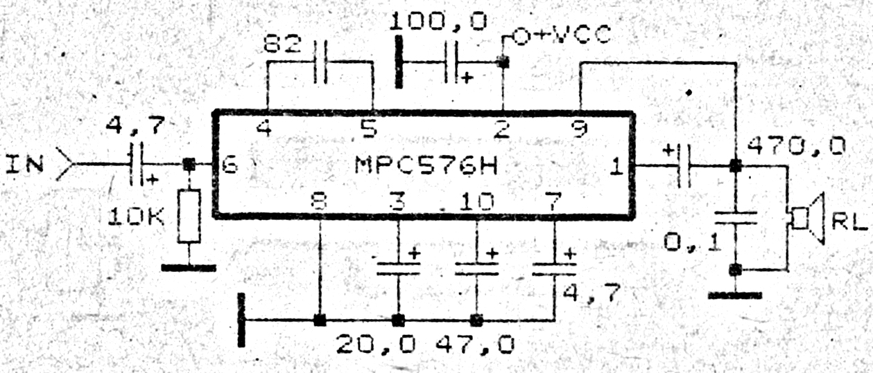
This amplifier circuit exhibits good sound quality. Although it does not provide high output power, it is capable of producing both soft and loud sounds reliably. The circuit utilizes a single IC, the MPC576H, along with several supporting components....
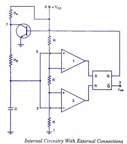
The 555 timer is a highly versatile integrated circuit that can be utilized to construct a wide variety of circuits. It can be effectively used without a detailed understanding of the function of each pin. The 555 timer is commonly...
Currently, a basic MOSFET amplifier or power amplifier is designed to deliver an output power of ±100 Watts RMS with an 8 Ohm load, or ±160 Watts RMS with a 4 Ohm load. The simplicity of this circuit results...
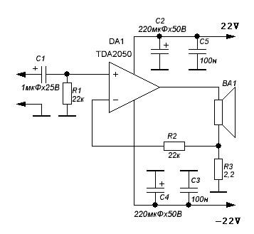
TDA2050 audio amplifier circuit diagram. The circuit incorporates environmental protection, where the output signal travels through connecting cables and the speaker’s network. In this case, the reactance of the circuit section connected to pin 4 of the chip is...
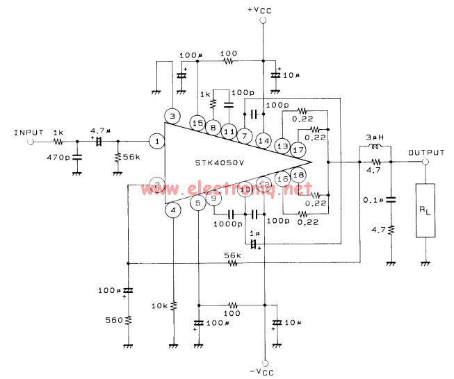
This 200-watt audio amplifier circuit diagram is based on the STK4050V high-power audio amplifier IC, designed to deliver up to 200 watts of audio power on a single channel. The STK4050V 200-watt audio amplifier circuit is pin-compatible with other...
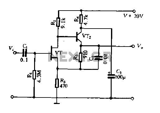
The Field Effect Transistor (FET) exhibits a high input impedance, allowing the construction of high input impedance amplifiers. However, as a FET amplifying device, the distributed capacitance and the Miller effect significantly increase input capacitance at high frequencies. Furthermore,...